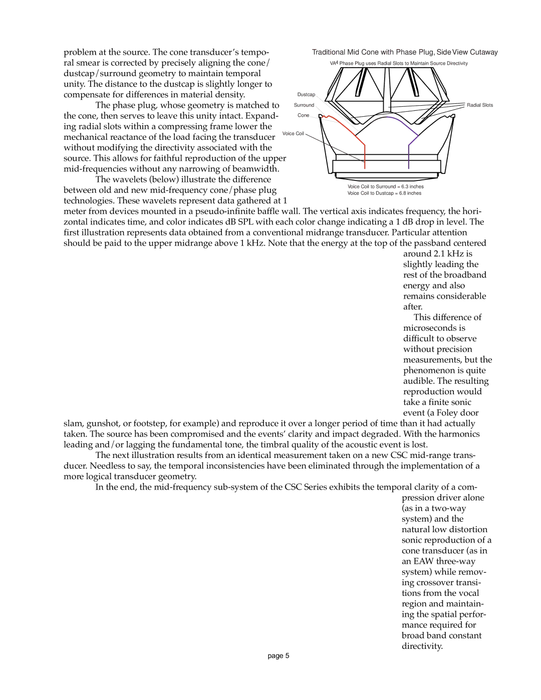
problem at the source. The cone transducer’s tempo- ral smear is corrected by precisely aligning the cone/ dustcap/surround geometry to maintain temporal unity. The distance to the dustcap is slightly longer to compensate for differences in material density.
The phase plug, whose geometry is matched to the cone, then serves to leave this unity intact. Expand-
ing radial slots within a compressing frame lower the
mechanical reactance of the load facing the transducer without modifying the directivity associated with the
source. This allows for faithful reproduction of the upper
The wavelets (below) illustrate the difference between old and new
meter from devices mounted in a
around 2.1 kHz is slightly leading the rest of the broadband energy and also remains considerable after.
This difference of microseconds is difficult to observe without precision measurements, but the phenomenon is quite audible. The resulting reproduction would take a finite sonic event (a Foley door
slam, gunshot, or footstep, for example) and reproduce it over a longer period of time than it had actually taken. The source has been compromised and the events’ clarity and impact degraded. With the harmonics leading and/or lagging the fundamental tone, the timbral quality of the acoustic event is lost.
The next illustration results from an identical measurement taken on a new CSC
In the end, the
page 5
