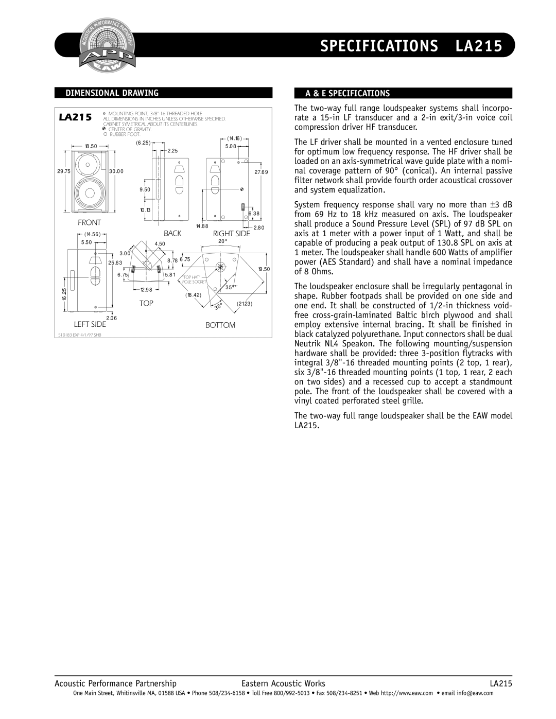
LA215 specifications
The EAW LA215 is a high-performance line array loudspeaker designed to meet the demands of professional audio applications. Known for its robust build and exceptional sound quality, the LA215 has become a staple in both live sound and installation scenarios.One of the main features of the LA215 is its dual 15-inch low-frequency drivers, offering deep, impactful bass that enhances the overall auditory experience. These drivers are engineered to provide clarity and power, making them suitable for a wide range of musical genres. Complementing the low-frequency drivers is a 3-inch diaphragm compression driver, which delivers crisp and detailed high frequencies. This combination allows the LA215 to reproduce a full spectrum of sound, lending itself well to both music and spoken word applications.
In terms of technology, the LA215 utilizes advanced acoustic design principles that enable smooth coverage and minimized distortion. The cabinet is constructed from high-quality plywood, ensuring durability while maintaining a lightweight profile for ease of transport and setup. The design features a fully integrated rigging system that allows for quick assembly and versatile configurations, often enabling deployment in both horizontal and vertical arrays.
Another distinctive characteristic of the EAW LA215 is its flexible connectivity options. The speaker is equipped with twist-lock connectors, simplifying the setup process and enhancing reliability during performance. This allows for seamless integration into existing sound systems, making the LA215 an accessible choice for sound engineers and event organizers alike.
The weather-resistant design of the LA215 also makes it suitable for outdoor events, as it is built to withstand the rigors of various environments. Additionally, it has undergone rigorous testing to ensure consistent performance across different settings and stages.
In summary, the EAW LA215 stands out due to its powerful dual 15-inch drivers, comprehensive frequency response, robust construction, and versatile rigging capabilities. These features, combined with its weather-resistant design and user-friendly setup, make the LA215 a formidable choice for professionals seeking reliable and high-quality sound reinforcement solutions. Whether for concerts, festivals, or permanent installations, the LA215 continues to impress audio engineers globally.

