UX8800 specifications
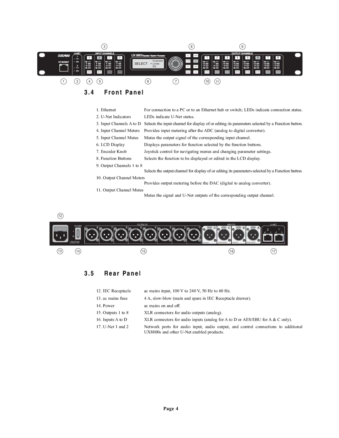
The EAW UX8800 is a powerful digital signal processor designed for professional audio applications, particularly in live sound reinforcement and installations. Known for its remarkable flexibility and advanced features, the UX8800 serves as a vital tool for sound engineers seeking to achieve optimal audio performance.One of the standout characteristics of the UX8800 is its extensive I/O capabilities. The unit offers up to 8 input and 8 output channels, which can be configured in various ways to accommodate different audio routing needs. This versatility makes it ideal for a range of applications, from concert touring to fixed installations in theaters and large venues.
The UX8800 employs advanced digital signal processing technologies that allow for intricate control of audio signals. It includes powerful algorithms for equalization, dynamic processing, delays, and crossover functions. This enables engineers to tailor the sound precisely to the acoustics of the venue, ensuring that every nuance of the audio is accurately reproduced.
One of the key features of the UX8800 is its user-friendly interface. Equipped with an intuitive PC-based control software, users can access and adjust settings through a visual representation of their audio system. This graphical interface simplifies the process of setting up and adjusting parameters, making it easier for sound technicians to make real-time changes during performances.
Additionally, the UX8800 provides a variety of connectivity options, including digital connectivity through AES/EBU, as well as analog connections. This ensures compatibility with a wide range of audio sources and systems, allowing for seamless integration into existing setups.
The device also supports advanced networking capabilities, enabling multiple units to be linked together for larger systems. This feature is particularly useful in larger venues where synchronization between multiple processors is essential for achieving cohesive sound.
With its robust construction and reliability, the EAW UX8800 is engineered to withstand the rigors of professional use. It is designed to operate efficiently in challenging environments, ensuring consistent performance night after night.
In conclusion, the EAW UX8800 is a premier choice for audio professionals seeking a powerful, flexible, and reliable digital signal processor. Its array of features, cutting-edge technologies, and intuitive interface make it an essential tool for anyone serious about achieving top-notch audio quality in any setting.

