ETHERNET

U-NET

1

2

U-NET

2 1

8

LED INDICATORS


8 . 1

E t h e r n e t


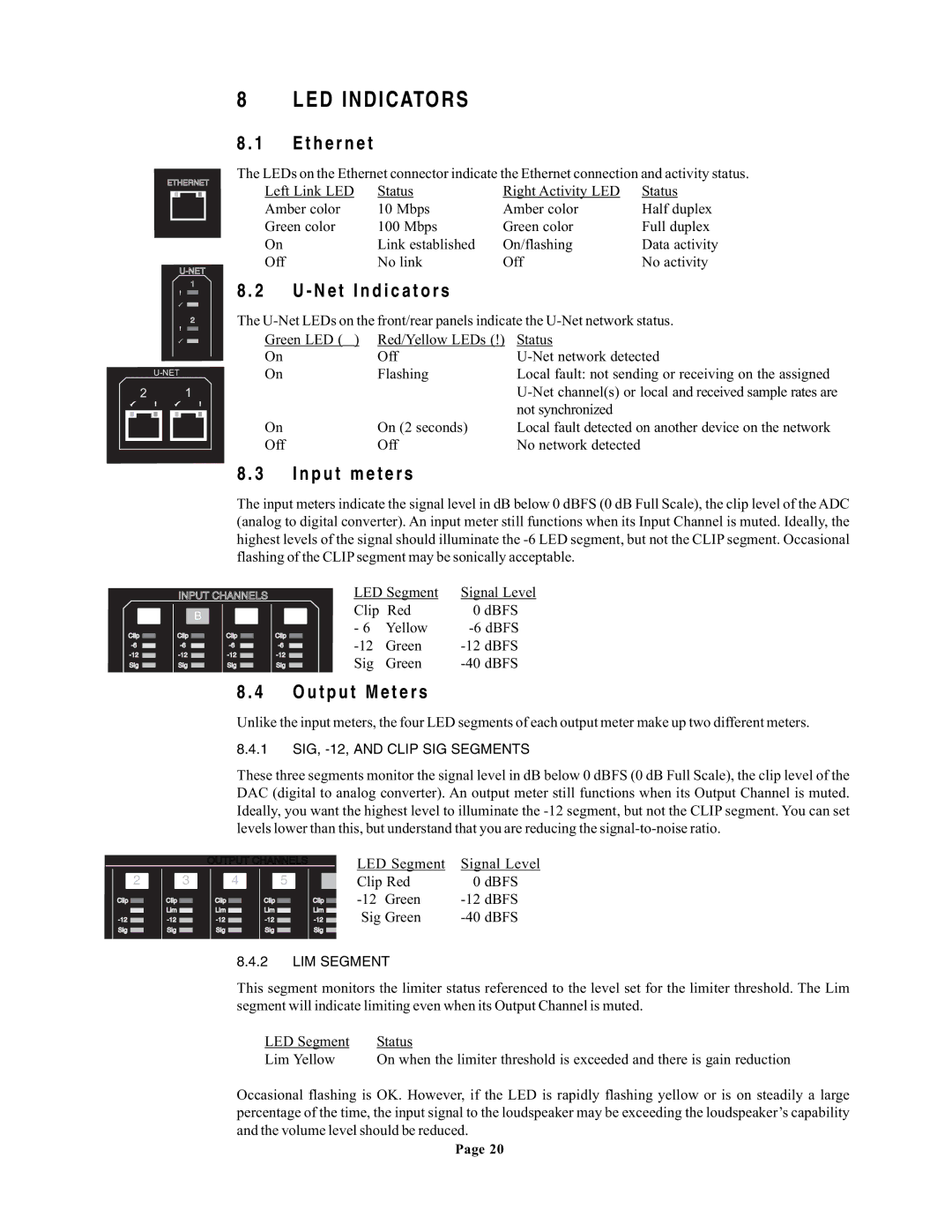
The LEDs on the Ethernet connector indicate the Ethernet connection and activity status.


Left Link LED

Status

Right Activity LED

Status


Amber color

10 Mbps

Amber color

Half duplex


Green color

100 Mbps

Green color

Full duplex


On

Link established

On/flashing

Data activity


Off

No link

Off

No activity

8 . 2

U - Net Indicators


The U-Net LEDs on the front/rear panels indicate the U-Net network status.


Green LED (￿)

Red/Yellow LEDs (!) Status


On

Off

U-Net network detected


On

Flashing

Local fault: not sending or receiving on the assigned


U-Net channel(s) or local and received sample rates are


not synchronized


On

On (2 seconds)

Local fault detected on another device on the network


Off

Off

No network detected


8 . 3 Input meters

The input meters indicate the signal level in dB below 0 dBFS (0 dB Full Scale), the clip level of the ADC (analog to digital converter). An input meter still functions when its Input Channel is muted. Ideally, the highest levels of the signal should illuminate the -6 LED segment, but not the CLIP segment. Occasional flashing of the CLIPsegment may be sonically acceptable.

A

Clip -6

-12

Sig

INPUT CHANNELS


LED Segment

Signal Level

B


C


D

Clip Red

0 dBFS


- 6

Yellow

-6 dBFS

Clip


Clip

Clip


-12

Green

-12 dBFS

-6


-6

-6


-12


-12

-12


Sig

Green

-40 dBFS

Sig


Sig

Sig


8 . 4 Output Meters

Unlike the input meters, the four LED segments of each output meter make up two different meters.

8.4.1 SIG, -12, AND CLIP SIG SEGMENTS

These three segments monitor the signal level in dB below 0 dBFS (0 dB Full Scale), the clip level of the DAC (digital to analog converter). An output meter still functions when its Output Channel is muted. Ideally, you want the highest level to illuminate the -12 segment, but not the CLIP segment. You can set levels lower than this, but understand that you are reducing the signal-to-noise ratio.


OUTPUT CHANNELS


LED Segment

Signal Level

2


3


4


5


6


Clip Red

0 dBFS

Clip


Clip


Clip


Clip


Clip


-12 Green

-12 dBFS


Lim


Lim


Lim


Lim


Lim


Sig Green

-40 dBFS

-12


-12


-12


-12


-12


Sig


Sig


Sig


Sig


Sig


8.4.2 LIM SEGMENT

This segment monitors the limiter status referenced to the level set for the limiter threshold. The Lim segment will indicate limiting even when its Output Channel is muted.

LED Segment

Status

Lim Yellow

On when the limiter threshold is exceeded and there is gain reduction

Occasional flashing is OK. However, if the LED is rapidly flashing yellow or is on steadily a large percentage of the time, the input signal to the loudspeaker may be exceeding the loudspeaker’s capability and the volume level should be reduced.

Page 20

Page 30
Image 30
EAW UX8800 owner manual LED Indicators, Net Indicators, Input meters, Output Meters

UX8800 specifications

The EAW UX8800 is a powerful digital signal processor designed for professional audio applications, particularly in live sound reinforcement and installations. Known for its remarkable flexibility and advanced features, the UX8800 serves as a vital tool for sound engineers seeking to achieve optimal audio performance.

One of the standout characteristics of the UX8800 is its extensive I/O capabilities. The unit offers up to 8 input and 8 output channels, which can be configured in various ways to accommodate different audio routing needs. This versatility makes it ideal for a range of applications, from concert touring to fixed installations in theaters and large venues.

The UX8800 employs advanced digital signal processing technologies that allow for intricate control of audio signals. It includes powerful algorithms for equalization, dynamic processing, delays, and crossover functions. This enables engineers to tailor the sound precisely to the acoustics of the venue, ensuring that every nuance of the audio is accurately reproduced.

One of the key features of the UX8800 is its user-friendly interface. Equipped with an intuitive PC-based control software, users can access and adjust settings through a visual representation of their audio system. This graphical interface simplifies the process of setting up and adjusting parameters, making it easier for sound technicians to make real-time changes during performances.

Additionally, the UX8800 provides a variety of connectivity options, including digital connectivity through AES/EBU, as well as analog connections. This ensures compatibility with a wide range of audio sources and systems, allowing for seamless integration into existing setups.

The device also supports advanced networking capabilities, enabling multiple units to be linked together for larger systems. This feature is particularly useful in larger venues where synchronization between multiple processors is essential for achieving cohesive sound.

With its robust construction and reliability, the EAW UX8800 is engineered to withstand the rigors of professional use. It is designed to operate efficiently in challenging environments, ensuring consistent performance night after night.

In conclusion, the EAW UX8800 is a premier choice for audio professionals seeking a powerful, flexible, and reliable digital signal processor. Its array of features, cutting-edge technologies, and intuitive interface make it an essential tool for anyone serious about achieving top-notch audio quality in any setting.