PAS-225 specifications
The Echo PAS-225 is a versatile and powerful outdoor power tool designed for homeowners and professionals who demand efficiency and reliability in garden maintenance tasks. This product stands out in the market due to its innovative features and robust technology that simplify yard work while maximizing performance.One of the main features of the Echo PAS-225 is its lightweight design. Weighing only about 10.5 pounds, this power head is easy to maneuver, reducing user fatigue during extended use. The unit is equipped with a low-emission, 21.2 cc professional-grade, 2-stroke engine, which not only delivers ample power for various attachments but also complies with stringent emission regulations, making it an environmentally friendly option.
The PAS-225 features a unique Power Agility system, allowing users to interchange multiple attachments with ease. This makes it a highly adaptable solution for a myriad of gardening tasks, from trimming and edging to blowing leaves and cultivating soil. The attachment system is user-friendly, enabling quick changes without the need for specialized tools.
Ergonomics play a crucial role in the design of the PAS-225. The padded handlebars provide a comfortable grip, which helps minimize strain during operation. Additionally, the unit boasts an easy start technology that ensures reliable ignition with minimal effort, setting a new standard in starting ease.
Another noteworthy technology in the PAS-225 is its vibration-dampening system. This reduces the amount of vibration transmitted to the user’s hands, enhancing comfort and control while operating the machine. It's particularly beneficial for prolonged use, making it easier to manage the tool safely.
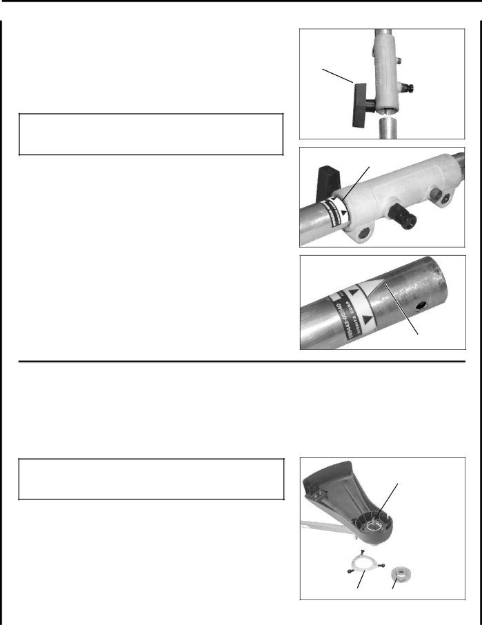
The fuel efficiency of the PAS-225 is another significant characteristic. Featuring a special engine design that optimizes fuel consumption, users can expect longer run times between refueling, enhancing productivity without frequent interruptions.
In terms of maintenance, the Echo PAS-225 is designed for durability and ease of care. The air filter is easily accessible, facilitating quick cleaning or replacement, and the engine is built to withstand rigorous use over time, ensuring longevity and reliability.
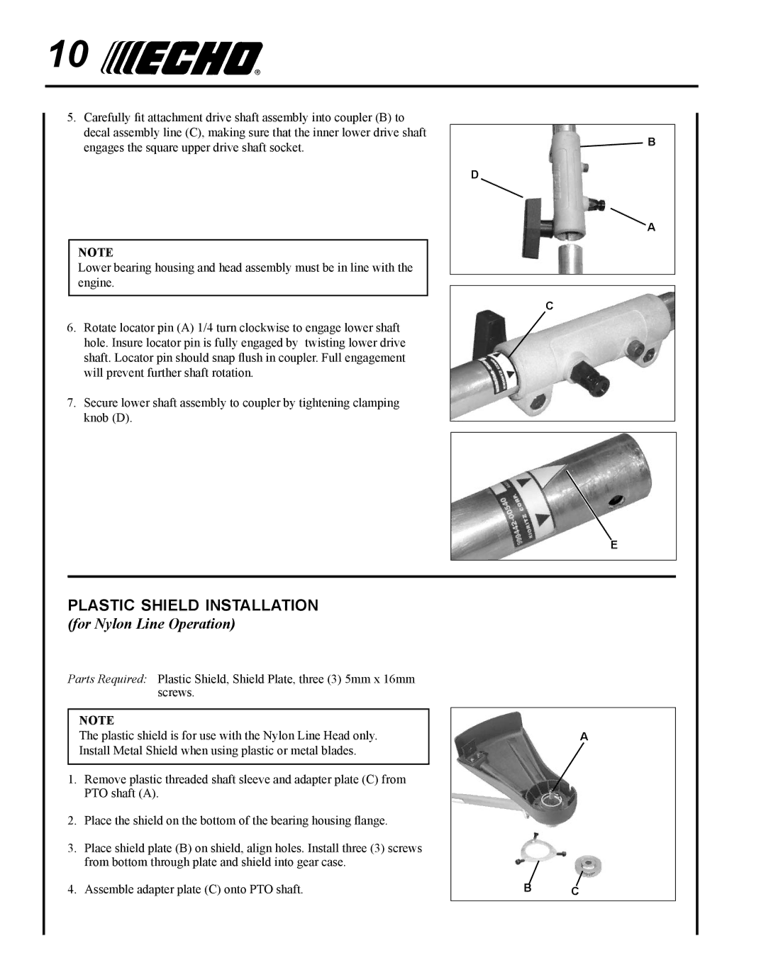
In summary, the Echo PAS-225 is a well-engineered, lightweight, and durable power tool that excels in versatility, performance, and user comfort. Whether for a homeowner looking to maintain their yard or a professional landscaper needing reliable equipment, the PAS-225 includes all the essential features and technologies to tackle a wide range of outdoor tasks with ease and efficiency.