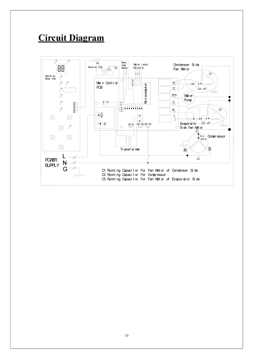
Circuit Diagram |
|
|
|
|
|
|
|
|
|
|
| ||
| 9C |
| Room | Wat er | Level |
|
| Condenser | Si de |
| |||
| Recei ver | PCB |
| Temp |
|
|
| ||||||
| 3C | Sensor | Det ect or |
|
| Fan Mot or |
|
| |||||
|
|
|
|
|
|
| |||||||
Oper at i on |
|
|
|
|
|
|
|
|
|
|
|
| C1 |
|
|
|
|
|
|
|
|
|
|
|
|
| |
Panel PCB |
|
|
|
|
|
|
|
|
|
|
|
|
|
| Mai n Cont r ol |
|
|
| er |
|
| HO |
|
|
| ||
| PCB |
|
|
|
|
|
|
|
|
|
| ||
|
|
|
|
| ocomput |
|
| LO |
| Cut - of f | |||
|
|
|
|
|
|
|
|
| Bump | Wat er |
| ||
|
|
|
|
|
|
| cr |
|
| HI | Pump |
| |
|
|
|
|
|
|
| Mi |
|
|
| |||
|
|
|
|
|
|
|
|
|
|
|
| ||
|
|
|
|
|
|
|
|
|
| MI |
|
| C3 |
|
| COM |
|
|
|
|
|
|
| LI |
|
|
|
|
| NO |
| AC- N | AC- N0 AC- N1 |
|
| Evapor at or | Cut - of f | ||||
|
|
|
|
|
|
|
|
|
|
| Si de Fan Mot or | ||
|
|
|
|
|
|
|
|
|
|
|
| C |
|
|
|
|
|
|
|
|
|
|
|
|
|
| Pr o- Compr essor |
|
|
|
|
|
|
|
|
|
|
|
|
| t ect or |
| L |
|
| Tr ansf or mer |
|
|
|
| R |
| S | ||
SUPPLYPOWER |
|
|
|
|
|
|
|
|
|
| C2 |
| |
N |
|
|
|
|
|
|
|
|
|
|
|
| |
| G | C1: Runni ng Capaci t or | For | Fan Mot or | of | Condenser | Si de |
| |||||
|
| C2: Runni ng Capaci t or | For | Compr essor |
|
|
|
|
| ||||
|
| C3: Runni ng Capaci t or | For | Fan Mot or | of | Evapor at or | Si de |
| |||||
|
|
|
| 19 |
|
|
|
|
|
|
|
|
|