Ei428 specifications
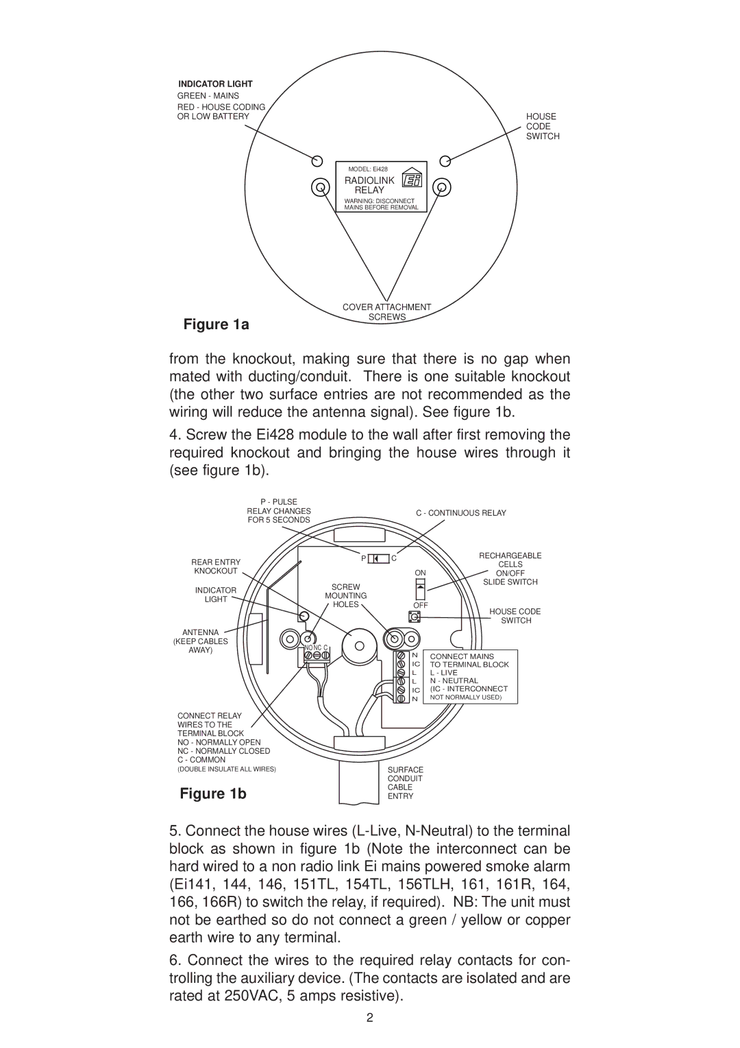
The Ei Electronics Ei428 smoke alarm is a cutting-edge device designed for dependable fire safety in both residential and commercial environments. Featuring advanced technologies and a commitment to quality, the Ei428 offers a wide range of features that enhance its functionality and reliability.One of the standout characteristics of the Ei428 is its dual-sensor technology. It employs both ionization and photoelectric sensing mechanisms to detect smoke effectively. The ionization sensor is particularly responsive to fast-flaming fires, while the photoelectric sensor is adept at identifying smoldering fires. This combination significantly increases the chances of early detection, thereby providing crucial time for occupants to respond during an emergency.
The Ei428 also incorporates a unique sealed lithium battery, which ensures a long life of up to 10 years. This battery eliminates the hassle of frequent battery replacements and delivers peace of mind to users, knowing that the device will remain functional throughout its lifespan. In addition, the built-in battery is designed to be tamper-proof, further enhancing the device's reliability.
Another remarkable feature of the Ei428 is its intelligent technology, which includes a self-test function. This automated testing feature regularly checks the sensor's functionality and alerts users to any issues, ensuring that the device remains in optimal working condition at all times. The alarm is also equipped with a loud 85 dB sounder, which provides audible alerts to make sure that occupants are aware of any potential fire danger, even in noisy environments.
In terms of design, the Ei428 has a compact and unobtrusive profile, allowing it to blend seamlessly into various decors. Its user-friendly interface includes a large test button for easy access during routine checks, promoting adherence to safety standards. The alarm's visual indicators provide additional information regarding the unit’s status, further simplifying the user's experience.
Overall, the Ei Electronics Ei428 smoke alarm stands as a testament to modern fire safety technology. It combines dual-sensor detection, long-lasting power, intelligent self-testing capabilities, and user-friendly design to deliver exceptional performance. Whether installed in homes, offices, or other spaces, the Ei428 is a vital asset in safeguarding lives against the threat of fire.

