Dialogic®
D/120JCT-LSU
Installation Guide
Copyright ©
All rights reserved.
1. Product Description
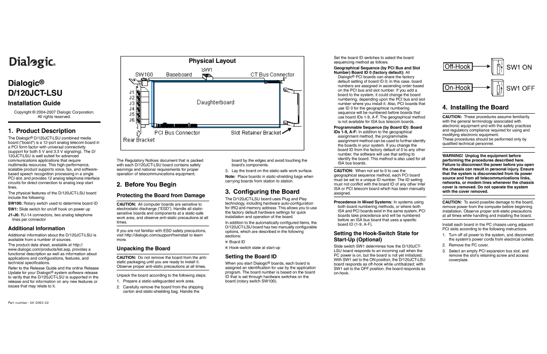
Physical Layout
Set the board ID switches to select the board sequencing method as follows.
Geographical Sequence (by PCI Bus and Slot Number) Board ID 0 (factory default): All
Dialogic® PCI boards can share the factory default setting of board ID 0; in this case, board numbers are assigned in ascending order based on the PCI bus and slot number. If you add a board to the system, it could change the board numbering, depending upon the PCI bus and slot number where you install it. Also, PCI boards that use ID 0 for the geographical numbering sequence will be numbered before boards that use board IDs
Programmable Sequence (by Board ID): Board
IDs
4. Installing the Board
CAUTION: These procedures assume familiarity with the general terminology associated with electronic equipment and with the safety practices and regulatory compliance required for using and modifying electronic equipment.
The Dialogic®
The physical features of the
SW100: Rotary switch used to determine board ID
SW1: Slide switch for on/off hook on power up
Additional Information
Additional information about the
The product data sheet, available at http:// www.dialogic.com/products/list.asp, provides a functional description as well as information about applications and configurations, features, and technical specifications.
Refer to the Release Guide and the online Release Update for your Dialogic® system software release to verify that the
The Regulatory Notices document that is packed with each
2. Before You Begin
Protecting the Board from Damage
CAUTION: All computer boards are sensitive to electrostatic discharge (“ESD”). Handle all static- sensitive boards and components at a
If you are not familiar with ESD safety precautions, visit http://dialogic.com/support/hwinstall to learn more.
Unpacking the Board
CAUTION: Do not remove the board from the anti- static packaging until you are ready to install it. Observe proper
Unpack the board according to the following steps:
1.Prepare a
2.Carefully remove the board from the shipping carton and
board by the edges and avoid touching the board's components.
3. Lay the board on the
Note: Place boards in
3. Configuring the Board
The
In addition to the automatically configured items, the
■Board ID
■
Setting the Board ID
When you start Dialogic® boards, each board is assigned an identification for use by the application program. The board number is based on the board ID that is set through hardware switches on the board (rotary switch SW100).
assignment method can be used to further identify the boards in your system. If you change the board ID from the factory default of 0 to any other number, the software will use that setting to identify the board. This method is also used for all ISA bus boards.
CAUTION: When not set to 0 to use the geographical sequence method, each PCI board must be set to a unique ID number. The ID setting must not conflict with the board ID of any other Intel ISA or PCI telecom board which has been manually assigned.
Precedence in Mixed Systems: In systems using both board numbering methods, or where both ISA and PCI boards exist in the same system, PCI boards take precedence and will be numbered before an ISA bus board that uses a specific board ID
Setting the Hook-Switch State for Start-Up (Optional)
Slide switch SW1 determines how the D/120JCT- LSU board responds to an incoming call when the PC power is on, but the board is not yet initialized.
With SW1 set to the ON position, the
These procedures should be performed only by qualified technical personnel.
WARNING! Unplug the equipment before performing the procedures described here. Failure to disconnect the power before you open the chassis can result in personal injury. Ensure that the system is disconnected from its power source and from all telecommunications links, networks, or modem lines whenever the chassis cover is removed. Do not operate the system with the cover removed.
CAUTION: To avoid possible damage to the board, remove power from the computer before beginning installation. Observe proper
Install each board in the PC chassis using adjacent PCI slots according to the following instructions.
1.Turn off all power to the system, and disconnect the system's power cords from electrical outlets.
2.Remove the PC cover.
3.Select an empty PCI expansion bus slot, and remove the slot's retaining screw and access coverplate.
Part number: