Installation and Wiring
through the strain relief fitting on the terminal cover plate (Figure 14). Hold the strain relief fit- tings tight around the cable.Tighten the strain relief screws first,then the horizontal screw. In the cases of insulated speaker wire and plenum cable,it is often possible to provide acceptable strain relief force by simply tightening the strain relief screws onto the terminal cover plate.
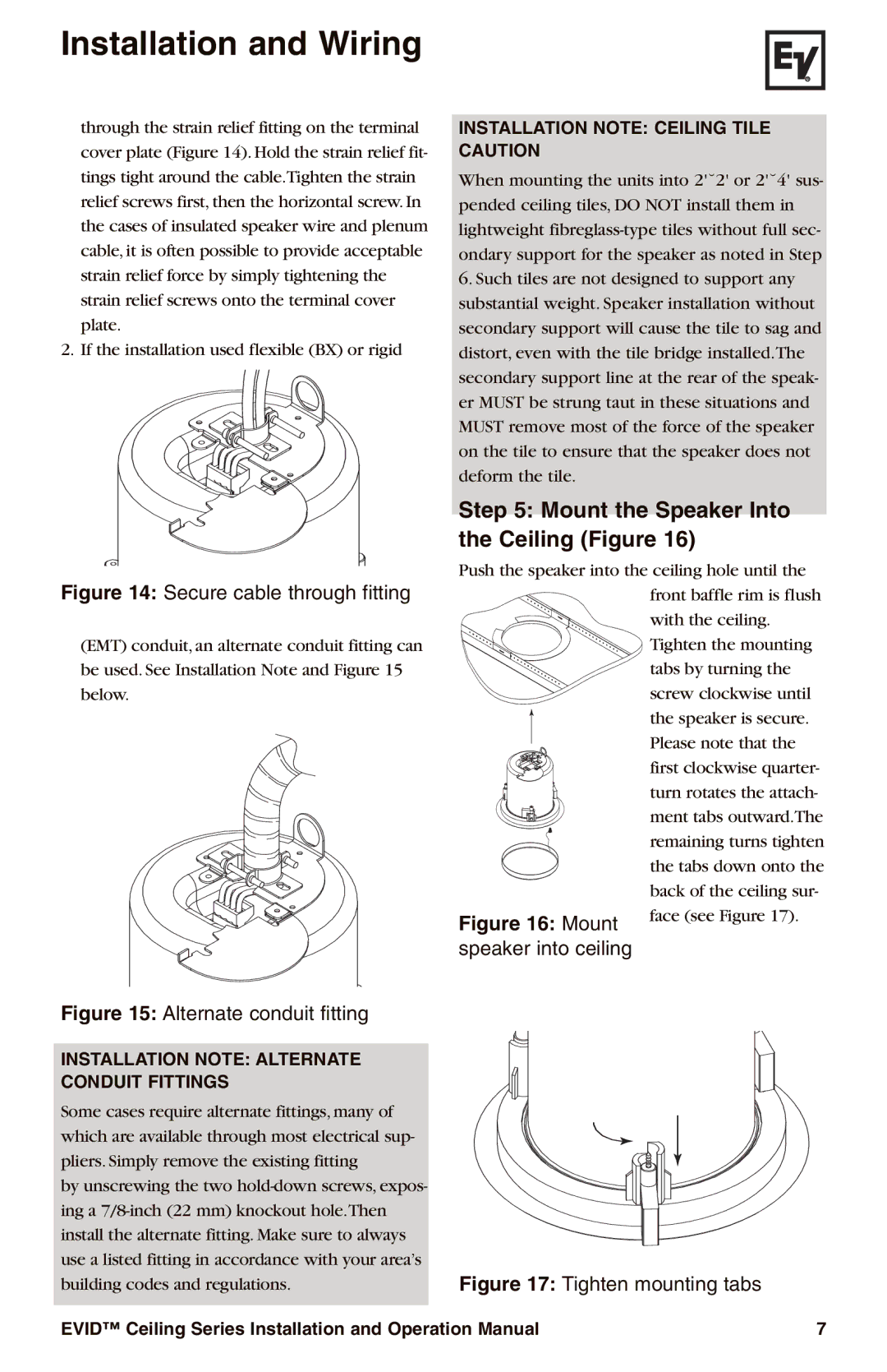
2. If the installation used flexible (BX) or rigid
Figure 14: Secure cable through fitting
(EMT) conduit, an alternate conduit fitting can be used. See Installation Note and Figure 15 below.
Figure 15: Alternate conduit fitting
INSTALLATION NOTE: ALTERNATE CONDUIT FITTINGS
Some cases require alternate fittings, many of which are available through most electrical sup- pliers. Simply remove the existing fitting
by unscrewing the two
INSTALLATION NOTE: CEILING TILE CAUTION
When mounting the units into 2'˘2' or 2'˘4' sus- pended ceiling tiles, DO NOT install them in lightweight
6.Such tiles are not designed to support any substantial weight. Speaker installation without secondary support will cause the tile to sag and distort, even with the tile bridge installed.The secondary support line at the rear of the speak- er MUST be strung taut in these situations and MUST remove most of the force of the speaker on the tile to ensure that the speaker does not deform the tile.
Step 5: Mount the Speaker Into the Ceiling (Figure 16)
Push the speaker into the ceiling hole until the
|
| front baffle rim is flush |
|
| with the ceiling. |
|
| Tighten the mounting |
|
| tabs by turning the |
|
| screw clockwise until |
|
| the speaker is secure. |
|
| Please note that the |
|
| first clockwise quarter- |
|
| turn rotates the attach- |
|
| ment tabs outward.The |
|
| remaining turns tighten |
|
| the tabs down onto the |
|
| back of the ceiling sur- |
Figure 16: | Mount | face (see Figure 17). |
|
speaker into ceiling
Figure 17: Tighten mounting tabs
EVID™ Ceiling Series Installation and Operation Manual | 7 |