30" GAS RANGE INSTALLATION INSTRUCTIONS
INSTALLATION AND SERVICE MUST BE PERFORMED BY A QUALIFIED INSTALLER.
IMPORTANT: SAVE FOR LOCAL ELECTRICAL INSPECTOR'S USE. READ AND SAVE THESE INSTRUCTIONS FOR FUTURE REFERENCE. OBSERVE ALL GOVERNING CODES AND ORDINANCES.
![]()
![]()
![]()
![]()
![]()
![]() If the information in this manual is not followed exactly, a fire or explosion may result causing property damage, personal injury or death.
If the information in this manual is not followed exactly, a fire or explosion may result causing property damage, personal injury or death.
FOR YOUR SAFETY:
—Do not store or use gasoline or other flammable vapors and liquids in the vicinity of this or any other appliance.
—WHAT TO DO IF YOU SMELL GAS:
•Do not try to light any appliance.
•Do not touch any electrical switch; do not use any phone in your building.
•Immediately call your gas supplier from a neighbor's phone. Follow the gas supplier's instructions.
•If you cannot reach your gas supplier, call the fire department.
—Installation and service must be performed by a qualified installer, service agency or the gas supplier.
Refer to your serial plate for applicable agency certification
Note: For
appliances installed in the state of Massachusetts see page 2.
29 7/8" Min.
(75.9 cm Min.)
WALL
C
B
If there is a wall: | See |
|
| |
5" Min. | note |
|
| |
(12.7 cm Min cm Min.) | 18" Min. | 13" Max. |
| |
(45.7 cm Min.) |
| |||
Left side | (33 cm Max.) | A | ||
| ||||
|
|
| ||
|
|
| D |
|
| G |
| If there is a wall: |
|
|
|
| ||
|
|
|
|
|
|
|
| |||
|
|
|
| 5" Min. |
|
|
|
| ||
F |
|
| (12.7 cm Min.) |
|
|
|
| |||
|
| Right side |
|
|
|
| ||||
|
|
|
|
|
|
|
| |||
|
|
|
|
|
|
|
| E |
| |
|
|
|
|
|
|
|
|
| ||
|
|
|
|
|
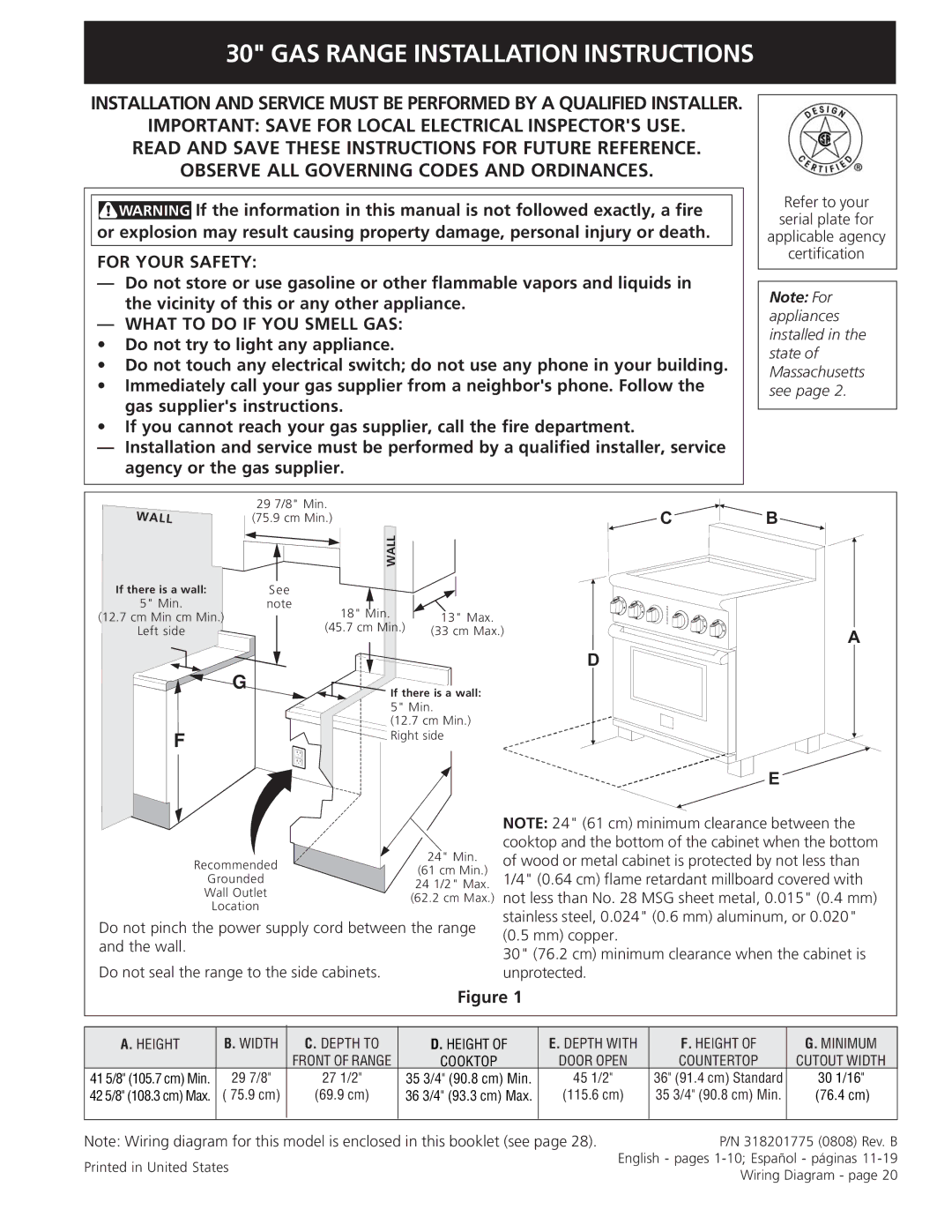
| NOTE: 24" (61 cm) minimum clearance between the | ||||
|
|
|
|
|
| |||||
|
|
|
|
| 24" Min. | cooktop and the bottom of the cabinet when the bottom | ||||
| Recommended |
|
| of wood or metal cabinet is protected by not less than | ||||||
|
|
| (61 cm Min.) | |||||||
| Grounded |
|
| 1/4" (0.64 cm) flame retardant millboard covered with | ||||||
|
|
| 24 1/2" Max. | |||||||
| Wall Outlet |
|
| (62.2 cm Max.) | not less than No. 28 MSG sheet metal, 0.015" (0.4 mm) | |||||
|
| Location |
|
|
| stainless steel, 0.024" (0.6 mm) aluminum, or 0.020" | ||||
Do not pinch the power supply cord between the range | ||||||||||
(0.5 mm) copper. |
|
| ||||||||
and the wall. |
|
|
|
|
|
| ||||
|
|
|
| 30" (76.2 cm) minimum clearance when the cabinet is | ||||||
|
|
|
|
|
| |||||
Do not seal the range to the side cabinets. |
| unprotected. |
|
| ||||||
|
|
|
|
| Figure 1 |
|
|
| ||
|
|
|
|
|
|
|
|
| ||
|
|
|
|
|
|
|
|
|
| |
A. HEIGHT | B. WIDTH | C. DEPTH TO | D. HEIGHT OF | E. DEPTH WITH | F. HEIGHT OF | G. MINIMUM | ||||
|
|
| FRONT OF RANGE | COOKTOP |
| DOOR OPEN | COUNTERTOP | CUTOUT WIDTH | ||
41 5/8" (105.7 cm) Min. | 29 7/8" | 27 1/2" |
| 35 3/4" (90.8 cm) Min. | 45 1/2" | 36" (91.4 cm) Standard | 30 1/16" | |||
42 5/8" (108.3 cm) Max. | ( 75.9 cm) | (69.9 cm) | 36 3/4" (93.3 cm) Max. | (115.6 cm) | 35 3/4" (90.8 cm) Min. | (76.4 cm) | ||||
|
|
|
|
|
|
|
|
| ||
Note: Wiring diagram for this model is enclosed in this booklet (see page 28). | P/N 318201775 (0808) Rev. B | |||||||||
Printed in United States |
|
|
|
| English - pages | |||||
|
| 1 |
|
| Wiring Diagram - page 20 | |||||
|
|
|
|
|
|
| ||||
