Burner cover/burner ring
Together with the burner ring the burner
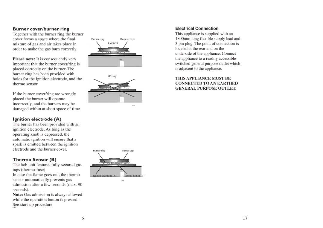
cover forms a space where the final | Burner ring | Burner cover |
mixture of gas and air takes place in |
| Correct |
order to make the gas burn correctly. |
|
|
Please note: It is consequently very important that the burner cover/ring is placed correctly on the burner. The
burner ring has been provided withWrong holes for the ignition electrode, and the
thermo sensor.
If the burner cover/ring are wrongly placed the burner will operate incorrectly, and the burners may be damaged within at short space of time.
Electrical Connection
This appliance is supplied with an 1800mm long flexible supply lead and 3 pin plug. The point of connection is located at the rear and on the underside of the appliance. Connect the appliance to a readily accessible switched general purpose outlet which is adjacent to the appliance.
THIS APPLIANCE MUST BE CONNECTED TO AN EARTHED GENERAL PURPOSE OUTLET.
Ignition electrode (A)
The burner has been provided with an ignition electrode. As long as the operating knob is depressed, the automatic ignition will ensure that a spark is emitted between the ignition electrode and the burner cover.
Thermo Sensor (B)
The hob unit features
In case the flame goes out, the thermo sensor automatically prevents gas admission after a few seconds (max. 90 seconds).
Note: Gas admission is always allowed while the operation button is pressed - See
Burner | Main nozzle |
Burner ring | Burner cap |
Ignition electrode (A) | T hermo Sensor (B) |
8 | 17 |