INSTALLATION INSTRUCTIONS
4.ELECTRICAL CONNECTION
Each appliance is accompanied by a complete connection and wiring diagram enclosed. This contains full details of the technical specifications (electrical rating, voltage, amperage etc.)
Check and ensure that the mains voltage agrees with the voltage given on the specification plate.
N.B.:
•The corresponding arrangements must be made
•The appliance must be connected to a potential
equalization system with a minimum conductor cross- section of 10 mm². The correspondingly marked connection terminal must be used for this purpose. When set up in block configuration, all appliances must be interconnected as potential equalization.
•The appliance is designed for connection to fixed lines. If the appliance is fitted directly to a masonry plinth without an appliance plinth, the supply must be located at the prescribed place. In this case, the protecting tube may not protrude from the plinth. If a CNS base is used, the protecting tube may not protrude more than 10 cm from the floor.
•After installation, the
•An isolating device working on all poles and with a minimum contact opening of 3 mm must be provided on site.
•When
•When using a faulty
4.1CONNECTION TERMINALS
A = Mains connection
G = Appliance outgoing section
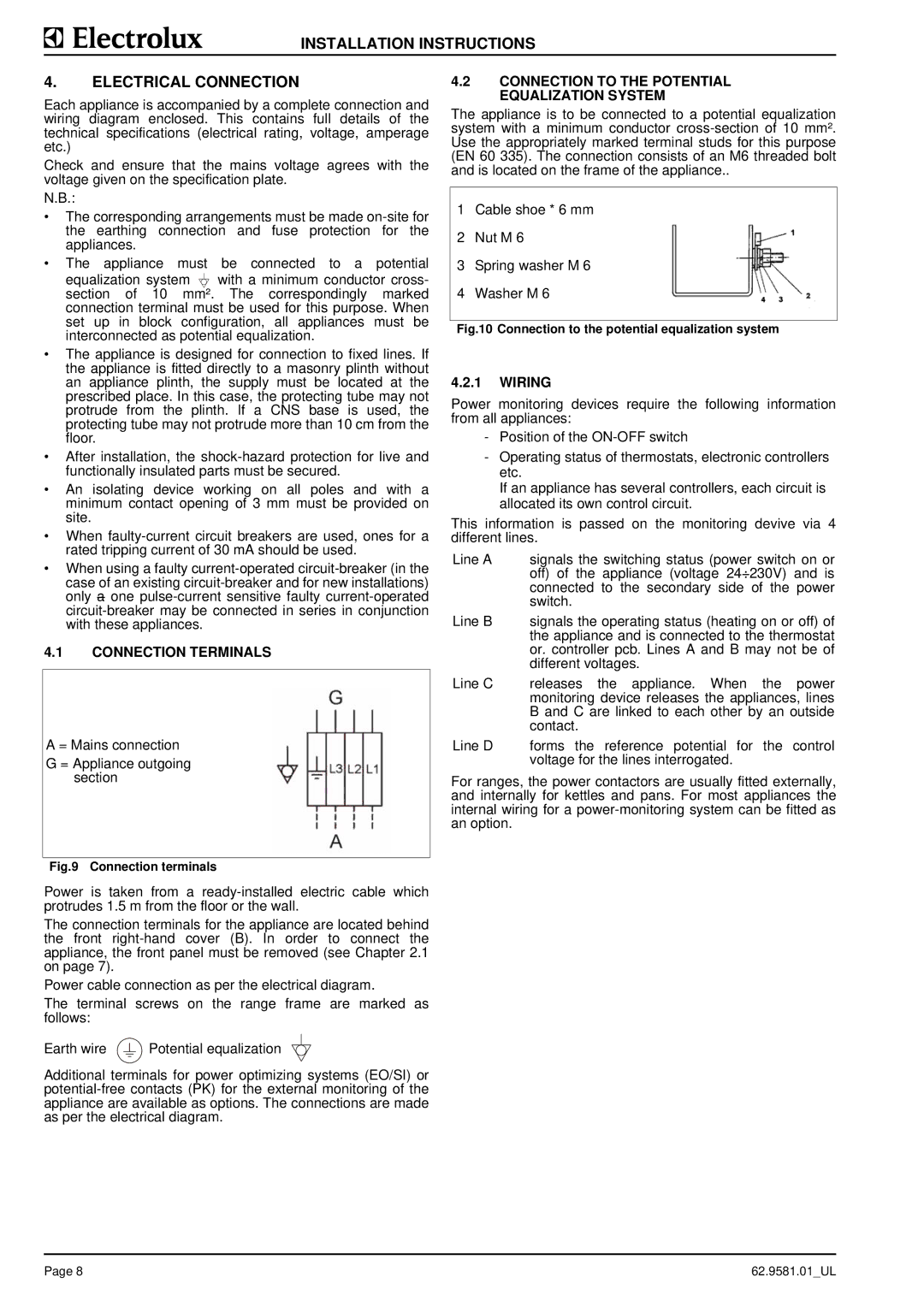
4.2CONNECTION TO THE POTENTIAL EQUALIZATION SYSTEM
The appliance is to be connected to a potential equalization system with a minimum conductor
1Cable shoe * 6 mm
2Nut M 6
3Spring washer M 6
4Washer M 6
Fig.10 Connection to the potential equalization system
4.2.1WIRING
Power monitoring devices require the following information from all appliances:
-Position of the
-Operating status of thermostats, electronic controllers etc.
If an appliance has several controllers, each circuit is allocated its own control circuit.
This information is passed on the monitoring devive via 4 different lines.
Line A signals the switching status (power switch on or off) of the appliance (voltage 24÷230V) and is connected to the secondary side of the power switch.
Line B signals the operating status (heating on or off) of the appliance and is connected to the thermostat or. controller pcb. Lines A and B may not be of different voltages.
Line C releases the appliance. When the power monitoring device releases the appliances, lines B and C are linked to each other by an outside contact.
Line D forms the reference potential for the control voltage for the lines interrogated.
For ranges, the power contactors are usually fitted externally, and internally for kettles and pans. For most appliances the internal wiring for a
Fig.9 Connection terminals
Power is taken from a
The connection terminals for the appliance are located behind the front
Power cable connection as per the electrical diagram.
The terminal screws on the range frame are marked as follows:
Earth wire ![]() Potential equalization
Potential equalization
Additional terminals for power optimizing systems (EO/SI) or
Page 8 | 62.9581.01_UL |