Elmo PSS User Guide | Product Description |
| |
|
|
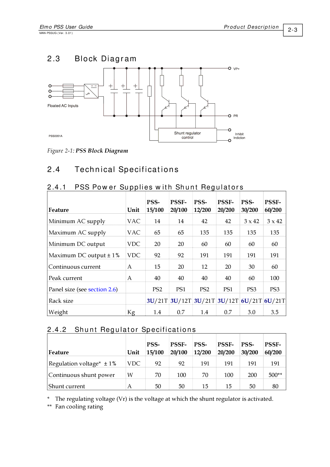
2.3Block Diagram
Figure 2-1: PSS Block Diagram
2.4Technical Specifications
2.4.1PSS Power Supplies with Shunt Regulators
|
| PSS- | PSSF- | PSS- | PSSF- | PSS- | PSSF- |
Feature | Unit | 15/100 | 20/100 | 12/200 | 20/200 | 30/200 | 60/200 |
Minimum AC supply | VAC | 14 | 14 | 42 | 42 | 3 x 42 | 3 x 42 |
Maximum AC supply | VAC | 65 | 65 | 135 | 135 | 135 | 135 |
Minimum DC output | VDC | 20 | 20 | 60 | 60 | 60 | 60 |
Maximum DC output ± 1% | VDC | 92 | 92 | 191 | 191 | 191 | 191 |
Continuous current | A | 15 | 20 | 12 | 20 | 30 | 60 |
Peak current | A | 40 | 40 | 40 | 40 | 60 | 100 |
Panel size (see section 2.6) |
| PS2 | PS1 | PS2 | PS1 | PS3 | PS3 |
Rack size |
| 3U/21T | 3U/12T | 3U/21T | 3U/12T | 6U/21T | 6U/21T |
Weight | Kg | 1.4 | 0.7 | 1.4 | 0.7 | 3.0 | 3.5 |
2.4.2Shunt Regulator Specifications
|
| PSS- | PSSF- | PSS- | PSSF- | PSS- | PSSF- |
Feature | Unit | 15/100 | 20/100 | 12/200 | 20/200 | 30/200 | 60/200 |
Regulation voltage* ± 1% | VDC | 92 | 92 | 191 | 191 | 191 | 191 |
Continuous shunt power | W | 70 | 100 | 70 | 100 | 200 | 500** |
Shunt current | A | 50 | 50 | 15 | 15 | 50 | 80 |
*The regulating voltage (Vr) is the voltage at which the shunt regulator is activated.
**Fan cooling rating