Contents
PSS 3U
PSS 6U
November
PSS User Guide
Important Notice
PSS F - 20 / 200 R
Product Catalog No
Contents
Chapter 1 Safety Information
Chapter 3 Installation
Chapter 2 Product Description
Chapter 1 Safety Information
1.1 Warnings
1.2 Cautions
1.3 Warranty Information
Safety Information
Table 2-1 PSS Terminal Description 3U Power Supplies
2.1 Standard Features
Chapter 2 Product Description
2.2 Fault Protection
Table 2-2 PSS Terminal Description 6U Power Supplies
2.3 Block Diagram
2.4 Technical Specifications
2.4.1 PSS Power Supplies with Shunt Regulators
2.4.2 Shunt Regulator Specifications
2.5 Dimensional Drawings
There are four basic sizes of the PSS/PSSF models
Panel mount PS1, for 3U/12T size Panel mount PS2, for 3U/21T size
Panel mount PS3, for 6U/21T size Rack mount
2.5.1 PS1 for PSSF-20/100 and PSSF-20/200
Figure 2-2 PS1 - Top View Figure 2-3 PS1 - Side View, Length
Figure 2-4 PS1 - Side View, Width
Elmo PSS User Guide
2.5.2 PS2 for PSS-15/100 and PSS-12/200
Figure 2-5 PS2 - Top View
Figure 2-6 PS2 - Side View, Length
Figure 2-7 PS2 - Side View, Width
2.5.3 PS3 for PSS-30/200 and PSSF-60/200
Figure 2-9 PS3 - Side View, Length
Figure 2-10 PS3 - Side View, Width
Figure 2-8 PS3 - Top View
2.5.4 Rack Mount
Figure 2-11 PSS Rack Mount 3U/12T Side View, Length
Figure 2-12 PSS Rack Mount 3U/12T Side View, Width
Elmo PSS User Guide
Chapter 3 Installation
3.2 Mounting and Wiring the PSS
3.2.1 Wiring Guidelines
3.2.2 AC Power Supplies
Figure 3-1 Isolated PSS Wiring
3.2.3 Wiring Diagrams
3.2.3.1 Isolated AC Supplies
3.3 Startup Procedures
3.3.1 Switching from Single-phase to Three-phase 3U only
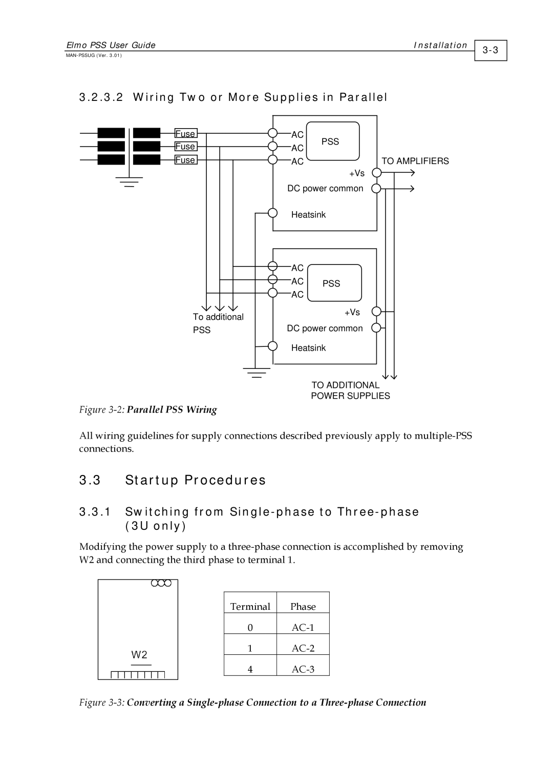
3.2.3.2 Wiring Two or More Supplies in Parallel
Figure 3-2 Parallel PSS Wiring
3.3.3 LED Diagnostics
3.3.2 Capacitor Reforming
To perform capacitor reforming
Noncompliance with these instructions may result in capacitor failure