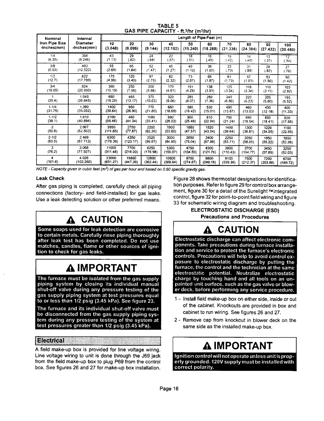
TABLE 5
GAS PIPE CAPACITY - ft.3/hr Im31hrl
Nominal |
| Internal |
|
|
|
| Length of | (m) |
|
|
| |||
Iron Pipe | Size | Diameter | 10 | 20 | 30 | 40 | 50 | 60 | 70 | 80 | 90 | 100 | ||
| ||||||||||||||
.InchesImm) | (3.048) | (6.096) | (9.144) | (12.192) | 115.2401 | (18.288) | (21.336) | (24.384) | (27.432 | (30.480) | ||||
|
| |||||||||||||
t/4 |
|
| 364 | 43 | 29 | 24 | 29 | 18 | 18 | 15 | 14 | 19 | 12 | |
(635) |
|
| ||||||||||||
| (9 246) | (1 13) | (.82) | (68) | (.57) | (81) | (45) | ( 401 | (40} | (3?) | (.34) | |||
|
| |||||||||||||
3/8 |
|
| 493 | 95 | 65 | 52 | 45 | 40 | 36 | 33 | 31 | 29 | 27 | |
(6,53) |
|
| ||||||||||||
| (12.5221 | (269) | (1.84) | (1 47) | (127) | (113) | (1.02) | (73) | (88) | (.82) | (75) | |||
|
| |||||||||||||
(127) |
| 622 | 175 | 120 | 97 | 82 | 73 | 66 | 61 | 57 | 53 | 50 | ||
| (17.799) | (496) | (340) | (2.75) | (232) | (2.07) | (1.87) | (173) | (101) | (1.50) | (142) | |||
|
| |||||||||||||
314 |
| .824 | 360 | 250 | 200 | 176 | 161 | 138 | 125 | 118 | 110 | 103 | ||
(19.05) |
| (20.930) | (10.19) | {706) | (566) | (4.81) | (4.28) | (3.91) | (3 54) | (3.34) | (3 11) | (292) | ||
1 |
| 1049 | 680 | 468 | 379 | 320 | 288 | 260 | 240 | 220 | 208 | !95 | ||
|
| |||||||||||||
(254) |
| (26.645) | (19,25) | (13.17) | (10,62) | (9,06) | (807) | (7.36) | (6 90) | (6.23) | (580) | (6.62) | ||
| 1.380 | 1400 | 960 | 770 | 660 | 580 | 630 | 490 | 460 | 430 | 400 | |||
(31.75) |
| (35.052) | (39.64) | (26.90) | (21.80) | (18,69) | (1642) | (15.01) | (13.67) | (13.031 | (1218) | (11.33) | ||
Io1/2 |
| 1.610 | 21 O0 | 466 | 1180 | 990 | 900 | 810 | 750 | 690 | 650 | 620 | ||
(381) |
| (40.894) | (59.46) | (41.34) | (3341) | (2803) | (2548) | (22.94) | (2124) | (19.54) | (1841) | (17,56) | ||
2 |
| 2.0_7 | 3950 | 2750 | 2200 | 1906 | 1680 | 1520 | 1400 | 1300 | 1220 | 1150 | ||
(5O.8) |
| (52.502) | (111.85) | (77,87) | (62.30) | (5380) | (47.57) | (43.041 | (3964) | (36.81) | (34.58) | (32.56) | ||
| 2469 | 6300 | 4350 | 9520 | 3000 | 2650 | 2400 | 2250 | 2050 | 1950 | 1880 | |||
(83.5) |
| (67 | 713) | (17839) | (12317) | (9967) | (84.95) | (75.04) | (67.96) | (63.71) | (58,05) | (55.22) | (52.38) | |
3 |
| 3068 | 11000 | 7700 | 6250 | 5300 | 4750 | 4300 | 3900 | 3700 | 3450 | 3250 | ||
(76.2) |
| |||||||||||||
| (77.927) | (31148) | (218.03) | (17698) | (150.07) | (134.50) | (121,76) | (110.43) | (104.77) | (97,69) | (92.03) | |||
|
| |||||||||||||
4 |
| 4 026 | 23000 | 15800 | 12800 | 10900 | 9700 | 8800 | St00 | 7500 | 7200 | 6700 | ||
(101.6) |
| |||||||||||||
| (102.260) | (651.27) | (447.39) | (362 44) | (308.64) | (274.67) | (249.t8) | (229.99) | (212.37) | (203.88) | (189.72) | |||
|
| |||||||||||||
NOTE - Capacity j 'iven in cubsc feet (m 3) o f gas per hour and based on O.60 specific gravity gas.
Leak Check
After gas piping is completed, carefully check all piping
connections (factory- and field-installed) for gas leaks.
Use a leak detecting solution or other preferred means.
CAUTION
Figu re 28 shows thermostat designations for identifica- tion purposes. Refer to figure 29 for control box arra nge- ment, figure 30 for a detail of the Surelight _integrated
control, figure 32 for
33 for schematic wiring diagram and troubleshooting,
ELECTROSTATIC DISCHARGE (ESD)
Precautions and Procedures
A, IMPORTANT 1
1 - Install field
2 - Remove cap from knockout in blower deck on the same side as the installed
iii::i:: i.................j
A field
from the field
box. See figures 26 and 27 for make-up box installation.
AIMPORTANT
Page 16