The following repair parts are available through independent Lennox dealers. When ordering parts, include the complete furnace model number listed on the unit rating plate. Example:
CABINET | PARTS |
| Gas manifold |
|
| ||||||
Cabinet | cap |
|
| Combustion |
| air inducer | |||||
Blower | panel |
|
| Main | burner | orifices | |||||
Upper | access | panel |
| Main | burners |
|
| ||||
CONTROL | PANEL | PARTS | gas valve | ||||||||
Ignitor |
|
|
|
|
| ||||||
|
|
|
|
|
| ||||||
Surelight TM integrated control board | Primary | limit | control | ||||||||
Flame |
| rollout | switch | ||||||||
Transformer |
|
|
|
| |||||||
|
|
|
|
|
|
|
|
| |||
Circuit | breaker |
|
| Filter and filter rack assembly | |||||||
Door interlock | switch |
| Flue transition |
| |||||||
|
|
|
|
|
|
| |||||
BLOWER | PARTS |
| Pressure switch | - high heat | |||||||
Blower | wheel |
|
| Pressure switch - low heat | |||||||
|
| Flame | sensor |
|
| ||||||
Motor |
|
|
|
|
|
| |||||
|
|
|
|
|
|
|
|
|
| ||
Motor mounting frame (Q4/5 only) | Sight | glass | and | grommet | |||||||
Rubber | boot | trap | |||||||||
Motor capacitor |
| ||||||||||
| Foam | manifold | gaskets | ||||||||
Blower housing | |||||||||||
Blower | housing |
| |||||||||
| Condensate pipe plug and adapter | ||||||||||
HEATING | PARTS |
| |||||||||
| Cold end header (collector) box | ||||||||||
Heat exchanger/coil | assembly | ||||||||||
|
|
|
|
|
| ||||||
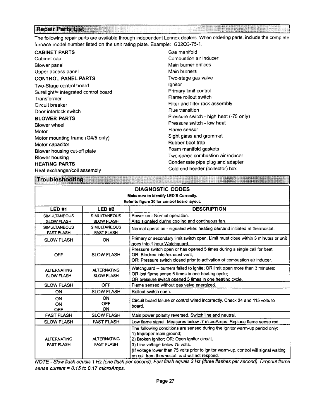
Make sure to Identify LED'SCorrectly.
Refer to figure 30 for control board layout.
LED #1 | LED #2 |
SIMULTANEOUS | SIMULTANEOUS |
SLOW FLASH | SLOWFLASH |
SIMULTANEOUS | SIMULTANEOUS |
FAST FLASH | FASTFLASH |
SLOW FLASH | ON |
OFF | SLOW FLASH |
DESCRIPTION
Power on - Normal operation.
Also siqnaleddudnq coolin,qand continuousfan
Normal operation- signaledwhen heating demand initiatedat thermostat.
Primary or secondary limit switch open. Limit must close within 3 minutes or unit qqes into 1 hour Watchouard,
Pressure switchopen or has opened 5 times during a single carl for heat; OR: Blocked inlet/exhaust vent;
OR: Pressure switchclosed prior to activationof combustion air inducer.
ALTERNATING | ALTERNATING |
SLOW FLASH | SLOW FLASH |
SLOW FLASH | OFF |
ON | SLOW FLASH |
ON | ON |
ON | OFF |
OFF | ON |
Watchguard - burners failed to ignite;OR limit open more than 3 minutes; OR lost flame sense 5 times in one heating cycle;
OR pressure switch opened 5 times in one heatino cvcle.
Flame sensed withoutgas valve energized. Rollout switchopen.
Cimuit board failure or controlwired incorrectly.Check 24 and 115 volts to
board.
FAST FLASH | SLOW FLASH | Main power polarity reversed. Switch line and neutral. | |
SLOW FLASH | FAST FLASH | Low flame signal. Measures below .7 micmAmps. Replace flame sense rod. | |
|
| The followingconditionsare sensed during the | |
|
| 1) Improper main ground; | |
ALTERNATING | ALTERNATING | 2) | Broken ignitor;OR: Open ignitorcircuit; |
FASTFLASH | FASTFLASH | 3) | Line voltage be{ow 75 volts. |
(If voltage towerthan 75 volts pdor to ignitor
NOTE - Slow flash equals 1 Hz (one flash per second). Fast flash equals 3 Hz (three flashes per second). Dropout flame
sense current = 0.15 to 0.17 microAmps.
Page 27