MODEL 140,141, and 142 sensors | TROUBLESHOOTING |
TROUBLESHOOTING
PROBLEM | PROBABLE CAUSE | SOLUTION |
|
|
|
Wiring is wrong. | Verify wiring. | |
| ||
|
|
|
| Temperature element is open or shorted. | Check temperature element for open or |
| short circuits. See Figure 14. | |
|
| |
|
|
|
| Sensor is not in the process stream. | Be sure the sensor is completely submerged |
| in the process stream. | |
|
| |
| Sensor has failed. | Perform isolation checks. See Figure 15. |
Noisy reading | Sensor is improperly installed in the | Be sure sensor is completely submerged |
| ||
| process stream. | in process stream. |
|
|
|
Reading seems wrong |
| Be sure the sensor is properly oriented in the |
| Bubbles trapped in the sensor. | |
(lower or higher than | pipe or flow cell. See Figure 1. Apply back | |
|
| |
expected) |
| pressure to the flow cell. |
|
| |
|
| Check that the temperature correction is |
| Wrong temperature correction algorithm. | appropriate for the sample. See analyzer |
|
| manual for more information. |
|
|
|
|
| Verify that the correct cell constant has |
|
| been entered in the analyzer and that the |
| Wrong cell constant. | cell constant is appropriate for the |
|
| conductivity of the sample. See analyzer |
|
| manual. |
Sluggish response | Electrodes are fouled. | Clean electrodes. |
| Sensor is installed in a dead area in the | Move the sensor to a location more |
| piping. | representative of the process liquid. |
|
|
|
|
|
|
|
|
|
|
|
| orange | ||
|
|
|
|
|
|
|
|
| |||
RTD |
|
|
|
|
|
|
|
| red | R | |
|
|
|
|
|
|
|
| ||||
|
|
|
|
|
| red | |||||
|
|
|
| ||||||||
|
|
|
|
|
|
|
|
|
| ||
terminal strip in sensor |
|
| gray | ||||||||
|
| ||||||||||
|
|
|
|
| junction box |
|
| ||||
|
|
|
|
|
|
|
|
|
| ||
|
|
|
|
|
|
|
|
|
|
|
|
|
|
|
|
| |||||||
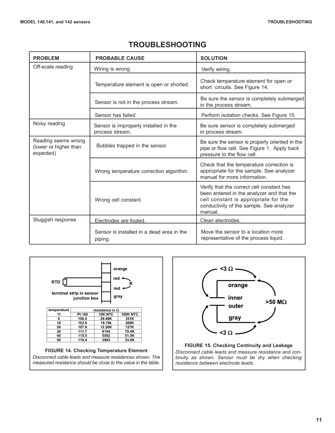
temperature | resistance in : |
| |||||||||
θC | Pt 100 |
| 10K NTC |
| 100K NTC | ||||||
0 |
|
|
|
| 100.0 |
| 29.49K |
| 351K | ||
10 |
|
|
|
| 103.9 |
| 18.79k |
| 208K | ||
20 |
|
|
|
| 107.8 |
| 12.26K |
| 127K | ||
30 |
|
|
|
| 111.7 |
| 8194 |
|
| 79.4K | |
40 |
|
|
|
| 115.5 |
| 5592 |
|
| 51.0K | |
50 |
|
|
|
| 119.4 |
| 3893 |
|
| 33.6K | |
FIGURE 14. Checking Temperature Element
Disconnect cable leads and measure resistances shown. The measured resistance should be close to the value in the table.
FIGURE 15. Checking Continuity and Leakage
Disconnect cable leads and measure resistance and con- tinuity as shown. Sensor must be dry when checking resistance between electrode leads.
11