2


INFERIOR VISTA


”76.

”54.1

”54.2


”8.2

”85.

”85.

”19.4

”59.5


”59.5


”73.6

”91.2


”58.1


POSTERIOR VISTA

DERECHA

FRONTAL VISTA

IZQUIERDA

LATERAL VISTA

LATERA VISTA


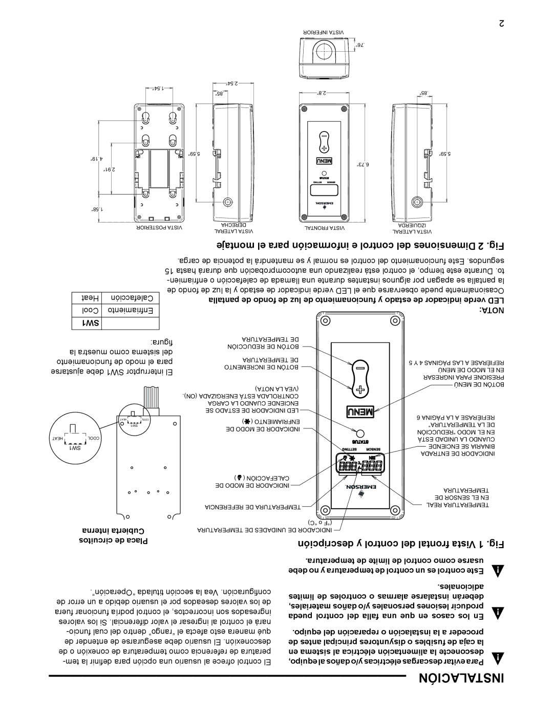
montaje el para información e control del Dimensiones 2 .Fig

Heat

Calefacción

Cool

Enfriamiento

SW1


.carga de potencia la mantendrá se y normal es control del funcionamiento Este .segundos 15 hasta durará que autocomprobación una realizando está control el tiempo, este Durante .to -enfriamien o calefacción de llamada una durante instantes algunos por apagan se pantalla la de fondo de luz la y estado de indicador verde LED el que observarse puede Ocasionalmente pantalla de fondo de luz de funcionamiento y estado de indicador verde LED NOTA:


figura:

TEMPERATURA DE


REDUCCIÓN DE BOTÓN


la muestra como sistema del


TEMPERATURA DE


funcionamiento de modo el para


5 Y 4 PÁGINAS LAS A REFIÉRASE

INCREMENTO DE BOTÓN


ajustarse debe SW1 interruptor El


MENÚ DE MODO EL EN


INGRESAR PARA PRESIONE


NOTA LA (VEA

)

MENÚ DE BOTÓN


(ON) ENERGIZADA ESTÁ CONTROLADA


.


CARGA LA CUANDO ENCIENDE


SE ESTADO DE INDICADOR LED


HEA T

COOL

) ( ENFRIAMIENTO


6 PÁGINA LA A REFIÉRASE


SW1


TEMPERATURA LA DE


DE MODO DE INDICADOR


“REDUCCIÓN MODO EL EN


HEAT

COO

L


EST UNIDAD LA CUANDO


SW1


ENCIENDE SE BINARIA


ENTRAD DE INDICADOR


( CALEFACCIÓN


)


DE MODO DE INDICADOR


TEMPERATURA


DE SENSOR EL EN


REFERENCIA DE TEMPERATURA


REAL TEMPERATURA


°C) o (°F


interna Cubierta

TEMPERATURA DE UNIDADES DE INDICADOR


circuitos de Placa


descripción y control del frontal Vista 1 .Fig


.temperatura de límite de control como usarse


debe no y temperatura de control un es control Este


.“Operación” titulada sección la Vea .configuración


.adicionales


límites de controles o alarmas instalarse deberán

de error un a debido usuario el por deseados valores los de

materiales, daños y/o personales lesiones producir

fuera funcionar podría control el incorrectos, son ingresados

pueda control del falla una que en casos los En

valores los Si .diferencial valor el ingresar al control el nará


-funcio cual del dentro “rango” el afecta esto manera qué

.equipo del reparación o instalación la a proceder


de entender de asegurarse debe usuario El .desconexión

de antes principal disyuntores o fusibles de caja la

de o conexión de temperatura como referencia de peratura

en sistema al eléctrica alimentación la desconecte

-tem la definir para opción una usuario al ofrece control El

equipo, al daños y/o eléctricas descargas evitar Para

INSTALACIÓN

Page 15
Image 15
Emerson 16E09-101 specifications Instalación

16E09-101 specifications

The Emerson 16E09-101 is a cutting-edge electronic controller designed specifically for heating, ventilation, and air conditioning (HVAC) systems. This controller stands out due to its advanced features, technologies, and characteristics that facilitate enhanced control and efficiency in managing climate conditions in both residential and commercial environments.

One of the main features of the 16E09-101 is its ability to support multiple HVAC components, including heat pumps, air conditioners, and ventilation systems. This versatility makes it suitable for a variety of applications. The controller is equipped with a user-friendly interface, which simplifies the setup process and allows users to monitor and adjust settings easily. The graphical display presents real-time data, including temperature, humidity, and system status, enabling quick diagnosis and troubleshooting of issues.

The Emerson 16E09-101 incorporates sophisticated control algorithms that optimize system performance while minimizing energy consumption. By utilizing advanced predictive logic, the controller can make adjustments to the operation of HVAC units based on real-time data inputs. This not only increases energy efficiency but also prolongs the lifespan of the equipment, offering cost savings over time.

Another key characteristic of the 16E09-101 is its built-in communication capabilities, which facilitate integration with building management systems (BMS). This feature enables centralized control and monitoring, allowing facility managers to oversee multiple units from a single interface. Additionally, its compatibility with various communication protocols ensures that it can easily connect to existing systems, further enhancing its utility.

The controller also supports a range of sensors, including temperature, humidity, and CO2 sensors, allowing for comprehensive monitoring of indoor air quality. This is particularly important in modern buildings where energy conservation must be balanced with occupant comfort.

In summary, the Emerson 16E09-101 is a highly capable and versatile electronic controller ideal for managing HVAC systems efficiently. With its advanced features, proactive control technologies, and robust communication capabilities, it offers significant benefits in terms of energy efficiency, system longevity, and user convenience. Whether for residential or commercial applications, the 16E09-101 exemplifies Emerson's commitment to innovation and quality in HVAC control solutions.