5 CHECK THERMOSTAT OPERATION
CONTINUED FROM PAGE 4
9Displays currently programmed set temperature (this is blank when SYSTEM switch is in the OFF position).
10Stage 1 & 2 Indicators: The thermostat shall indicate when the first and second stage is energized except in emergency mode. The icon is STG 1 for the first stage energized. The icons for the first and second stage energized are STG1+2 located in the lower right side of the display.
Configuration Menu
The configuration menu allows you to set certain thermostat operating characteristics to your system or personal requirements.
The menu mode may be exited by pressing the system key to change from the OFF mode or after 15 minutes has elapsed with no keypad activity.
2.
3.Fast or Slow Cycle Selection – The factory default setting is fast cycle, which cycles 1st stage at approximately 1.2˚F and 2nd stage 0.75˚F. If you prefer slow cycle, press the tempera- ture key to change to SL. The 1st stage and 2nd stage would be 1.5˚F and 1.2˚F respectively.
4.Select backlit display – (Not available on earlier models.) The display backlight improves display contrast in low lighting conditions. Selecting backlight ON will keep the light on con- tinuously. Selecting backlight OFF will keep the light off.
5.In the run mode, if the setpoint temperature is manually raised by 3°F (2°C) or more above the actual temperature with the TEMPERATURE UP key, and the fast second stage feature is enabled, FA on, the second stage will energize immediately.
With FA off, second stage will not energize until the setpoint temperature is 1°F or more above actual temperature for more than ten minutes.
6.Select Compressor Lockout CL OFF or ON – Selecting CL ON will cause the thermostat to wait 5 minutes before turning on the compressor if the heating and cooling system loses power. It will also wait 5 minutes minimum between cooling and heating cycles. This is intended to help protect the compressor from short cycling. Some newer compressors already have a time delay built in and do not require this feature. Your com- pressor manufacturer can tell you if the lockout feature is already present in their system. When the thermostat compres- sor time delay occurs it will flash the Snowflake and Flame Icons for about five minutes.
7.Select Temperature Display Adjustment 3 LO to 3 HI – Allows you to adjust the room temperature display up to 3° higher or lower. Your thermostat was accurately calibrated at the factory but you have the option to change the display temperature to match your previous thermostat. The current or adjusted room temperature will be displayed on the left side of the display.
8.˚F or ˚C Selection – The factory default setting for temperature display is Fahrenheit. If you want the temperature in Celcius, press temperature key to change to ˚C.
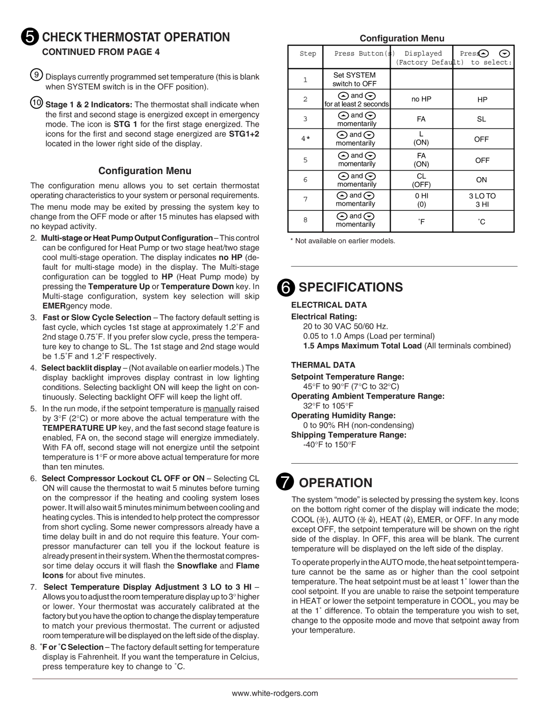
Configuration Menu
Step | Press Button(s) |
| Displayed |
| Press |
|
| (Factory Default) to select: | |||
|
|
|
|
|
|
1 | Set SYSTEM |
|
|
|
|
switch to OFF |
|
|
|
| |
|
|
|
|
| |
|
|
|
|
|
|
2 | and |
| no HP |
| HP |
for at least 2 seconds |
|
| |||
|
|
|
|
| |
3 | and |
| FA |
| SL |
momentarily |
|
| |||
|
|
|
|
| |
4* | and |
| L |
| OFF |
momentarily |
| (ON) |
| ||
|
|
|
| ||
|
|
|
|
|
|
5 | and |
| FA |
| OFF |
momentarily |
| (ON) |
| ||
|
|
|
| ||
|
|
|
|
|
|
6 | and |
| CL |
| ON |
momentarily |
| (OFF) |
| ||
|
|
|
| ||
7 | and |
| 0 HI |
| 3 LO TO |
momentarily |
| (0) |
| 3 HI | |
|
|
| |||
|
|
|
|
|
|
8 | and |
| ˚F |
| ˚C |
momentarily |
|
| |||
|
|
|
|
| |
|
|
|
|
|
|
* Not available on earlier models.
6 SPECIFICATIONS
ELECTRICAL DATA
Electrical Rating:
20 to 30 VAC 50/60 Hz.
0.05 to 1.0 Amps (Load per terminal)
1.5Amps Maximum Total Load (All terminals combined)
THERMAL DATA
Setpoint Temperature Range:
45°F to 90°F (7°C to 32°C)
Operating Ambient Temperature Range:
32°F to 105°F
Operating Humidity Range:
0 to 90% RH
Shipping Temperature Range:
7 OPERATION
The system “mode” is selected by pressing the system key. Icons on the bottom right corner of the display will indicate the mode; COOL (![]() ), AUTO (
), AUTO (![]()
![]() ), HEAT (
), HEAT (![]() ), EMER, or OFF. In any mode except OFF, the setpoint temperature will be shown on the right side of the display. In OFF, this area will be blank. The current temperature will be displayed on the left side of the display.
), EMER, or OFF. In any mode except OFF, the setpoint temperature will be shown on the right side of the display. In OFF, this area will be blank. The current temperature will be displayed on the left side of the display.
To operate properly in the AUTO mode, the heat setpoint tempera- ture cannot be the same as or higher than the cool setpoint temperature. The heat setpoint must be at least 1˚ lower than the cool setpoint. If you are unable to raise the setpoint temperature in HEAT or lower the setpoint temperature in COOL, you may be at the 1˚ difference. To obtain the temperature you wish to set, change to the opposite mode and move that setpoint away from your temperature.