Finished Bore Mounting

1.6  Mounting Of Reducer with Finished Bore Shaft

1.6.1  Check the internal bore of the reducer and make sure the snap ring and washer are in the end of the shaft bore opposite the entry side of the driven shaft.

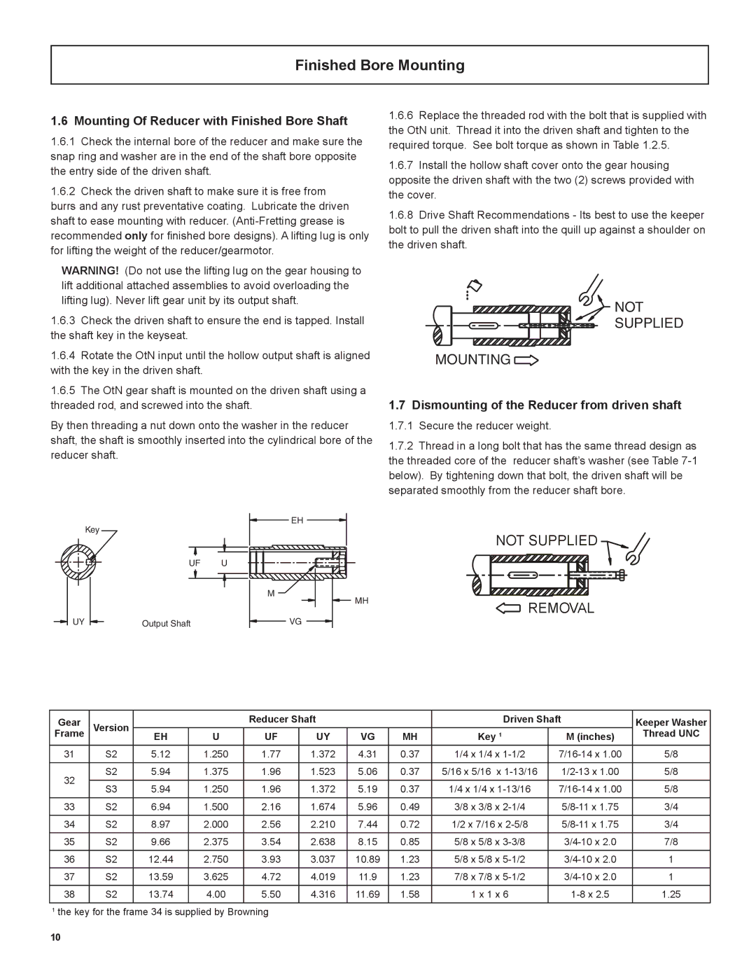
1.6.2  Check the driven shaft to make sure it is free from burrs and any rust preventative coating.  Lubricate the driven shaft to ease mounting with reducer. (Anti-Fretting grease is recommended only for finished bore designs). A lifting lug is only for lifting the weight of the reducer/gearmotor.

WARNING!  (Do not use the lifting lug on the gear housing to lift additional attached assemblies to avoid overloading the lifting lug). Never lift gear unit by its output shaft.

1.6.3  Check the driven shaft to ensure the end is tapped. Install the shaft key in the keyseat.

1.6.6  Replace the threaded rod with the bolt that is supplied with the OtN unit.  Thread it into the driven shaft and tighten to the required torque.  See bolt torque as shown in Table 1.2.5.

1.6.7  Install the hollow shaft cover onto the gear housing opposite the driven shaft with the two (2) screws provided with the cover.

1.6.8  Drive Shaft Recommendations - Its best to use the keeper bolt to pull the driven shaft into the quill up against a shoulder on the driven shaft.

NOT

SUPPLIED

1.6.4  Rotate the OtN input until the hollow output shaft is aligned with the key in the driven shaft.

1.6.5  The OtN gear shaft is mounted on the driven shaft using a threaded rod, and screwed into the shaft.

By then threading a nut down onto the washer in the reducer shaft, the shaft is smoothly inserted into the cylindrical bore of the reducer shaft.

MOUNTING

1.7  Dismounting of the Reducer from driven shaft

1.7.1  Secure the reducer weight.

1.7.2  Thread in a long bolt that has the same thread design as the threaded core of the reducer shaft’s washer (see Table 7-1 below).  By tightening down that bolt, the driven shaft will be separated smoothly from the reducer shaft bore.

Key

EH

NOT SUPPLIED

UF

U

UY

Output Shaft

M

MH


REMOVAL


VG


Gear

Version


Reducer Shaft


Driven Shaft

Keeper Washer

Frame

EH

U

UF

UY

VG

MH

Key 1

M (inches)

Thread UNC

31

S2

5.12

1.250

1.77

1.372

4.31

0.37

1/4 x 1/4 x 1-1/2

7/16-14 x 1.00

5/8


32

S2

5.94

1.375

1.96

1.523

5.06

0.37

5/16 x 5/16 x 1-13/16

1/2-13 x 1.00

5/8


S3

5.94

1.250

1.96

1.372

5.19

0.37

1/4 x 1/4 x 1-13/16

7/16-14 x 1.00

5/8


33

S2

6.94

1.500

2.16

1.674

5.96

0.49

3/8 x 3/8 x 2-1/4

5/8-11 x 1.75

3/4


34

S2

8.97

2.000

2.56

2.210

7.44

0.72

1/2 x 7/16 x 2-5/8

5/8-11 x 1.75

3/4


35

S2

9.66

2.375

3.54

2.638

8.15

0.85

5/8 x 5/8 x 3-3/8

3/4-10 x 2.0

7/8


36

S2

12.44

2.750

3.93

3.037

10.89

1.23

5/8 x 5/8 x 5-1/2

3/4-10 x 2.0

1


37

S2

13.59

3.625

4.72

4.019

11.9

1.23

7/8 x 7/8 x 5-1/2

3/4-10 x 2.0

1


38

S2

13.74

4.00

5.50

4.316

11.69

1.58

1 x 1 x 6

1-8 x 2.5

1.25

1the key for the frame 34 is supplied by Browning

10

Page 10
Image 10
Emerson 3000 installation instructions Finished Bore Mounting, Mounting Of Reducer with Finished Bore Shaft

3000 specifications

The Emerson 3000 is a cutting-edge control system designed to enhance the efficiency, reliability, and precision of industrial operations. Employed across various sectors such as oil and gas, pharmaceutical, food and beverage, and power generation, the Emerson 3000 has gained recognition for its robustness and versatility.

One of the main features of the Emerson 3000 is its advanced process control capability. With integrated control algorithms, it can optimize complex processes in real-time, resulting in significant improvements in production rates and reduced operational costs. The system's predictive analytics capabilities enable operators to anticipate equipment failures and maintenance needs, allowing for proactive management and minimizing downtime.

The Emerson 3000 features a modular architecture, providing flexibility for scaling and customization. Operators can easily tailor the system to fit specific application needs, whether it requires additional control loops or integration with other systems. This adaptability is particularly beneficial for facilities planning for future expansions or modifications.

Another technology highlight of the Emerson 3000 is its seamless integration with the latest Internet of Things (IoT) advancements. The system is designed to communicate effectively with a variety of smart devices and sensors, harnessing data to create insightful analytics that drive operational excellence. This connectivity empowers businesses to leverage big data for improved decision-making and increased agility.

Additionally, the Emerson 3000 incorporates state-of-the-art cybersecurity measures to safeguard critical data and operations. With built-in security protocols and regular updates, the system protects against emerging cyber threats, ensuring the integrity of the control network.

User experience is also a focal point of the Emerson 3000. The intuitive graphical user interface presents complex data in a user-friendly format, making it easier for operators to monitor system performance and respond to alerts quickly. This ease of use contributes to enhanced safety and operational efficiency.

In summary, the Emerson 3000 represents a fusion of advanced process control, modular design, IoT connectivity, robust cybersecurity, and user-centric interface, making it an ideal choice for industries seeking to enhance their operational performance while adapting to ever-evolving technological landscapes.