INSTALLATION (continued)

Harnesses

The transfer switch is connected to the left side of the controller by a plug-in harness (two plugs).

Engine Starting Contacts

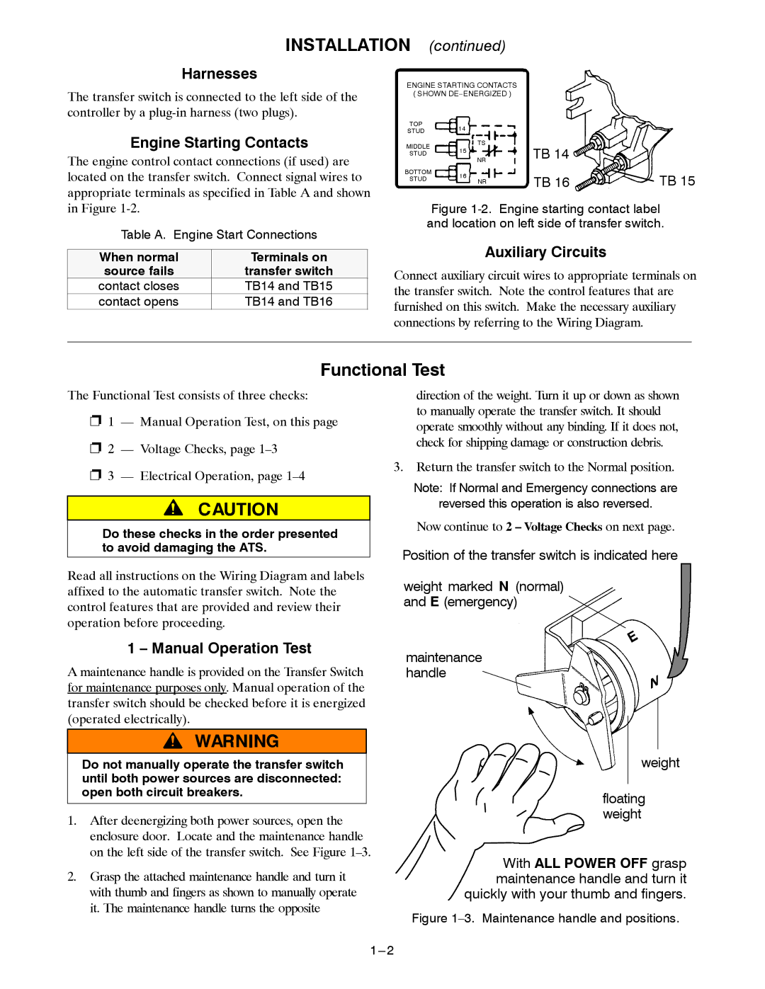
The engine control contact connections (if used) are located on the transfer switch. Connect signal wires to appropriate terminals as specified in Table A and shown in Figure 1-2.

Table A. Engine Start Connections

When normal

Terminals on

source fails

transfer switch

contact closes

TB14 and TB15

contact opens

TB14 and TB16

ENGINE STARTING CONTACTS ( SHOWN DE–ENERGIZED )

TOP

14


STUD


MIDDLE

TS

TB 14


NR


STUD

15


BOTTOM

16

TB 16

TB 15

STUD

NR


Figure 1-2. Engine starting contact label and location on left side of transfer switch.

Auxiliary Circuits

Connect auxiliary circuit wires to appropriate terminals on the transfer switch. Note the control features that are furnished on this switch. Make the necessary auxiliary connections by referring to the Wiring Diagram.

Functional Test

The Functional Test consists of three checks:

S1 — Manual Operation Test, on this page

S2 — Voltage Checks, page 1–3

S3 — Electrical Operation, page 1–4

Do these checks in the order presented to avoid damaging the ATS.

direction of the weight. Turn it up or down as shown to manually operate the transfer switch. It should operate smoothly without any binding. If it does not, check for shipping damage or construction debris.

3.Return the transfer switch to the Normal position.

Note: If Normal and Emergency connections are

reversed this operation is also reversed.

Now continue to 2 – Voltage Checks on next page.

Position of the transfer switch is indicated here

Read all instructions on the Wiring Diagram and labels affixed to the automatic transfer switch. Note the control features that are provided and review their operation before proceeding.

1 – Manual Operation Test

A maintenance handle is provided on the Transfer Switch for maintenance purposes only. Manual operation of the transfer switch should be checked before it is energized (operated electrically).

Do not manually operate the transfer switch until both power sources are disconnected: open both circuit breakers.

1.After deenergizing both power sources, open the enclosure door. Locate and the maintenance handle on the left side of the transfer switch. See Figure 1–3.

2.Grasp the attached maintenance handle and turn it with thumb and fingers as shown to manually operate it. The maintenance handle turns the opposite

1---2

weight marked N (normal) and E (emergency)

maintenance handle

weight

floating weight

With ALL POWER OFF grasp maintenance handle and turn it quickly with your thumb and fingers.

Figure 1–3. Maintenance handle and positions.

Page 4
Image 4
Emerson 7000 Harnesses, Engine Starting Contacts, Auxiliary Circuits, Manual Operation Test, Source fails Transfer switch

7000 specifications

The Emerson 7000 series is a versatile and advanced automation solution designed for modern industrial environments. Renowned for its reliability, scalability, and performance, the Emerson 7000 series is tailored to meet the complex demands of various industries, including oil and gas, chemical manufacturing, power generation, and food and beverage.

At the heart of the Emerson 7000 series is its powerful and flexible architecture. This series integrates seamlessly with existing systems, allowing for easy upgrades without disrupting ongoing processes. The modular design enables users to customize their setups according to their specific needs, providing unmatched adaptability in dynamic operations.

One of the standout features of the Emerson 7000 is its intelligent diagnostics capabilities. This technology leverages advanced algorithms and machine learning to predict equipment failures and maintenance needs, thus minimizing unplanned downtime. By continuously monitoring critical parameters, the system provides operators with actionable insights, enhancing operational efficiency and safety.

The Emerson 7000 series also focuses on user-friendly interfaces. Its intuitive design allows operators to quickly navigate complex data and analytics, facilitating quicker decision-making. The human-machine interface (HMI) provides a clear visual representation of processes, empowering users to manage operations effectively.

Another cutting-edge technology in the Emerson 7000 series is its cybersecurity measures. With the increasing threat of cyber-attacks in industrial environments, Emerson has prioritized the integration of robust security protocols. These features protect sensitive data and ensure the integrity of operations, safeguarding organizations from potential breaches.

Additionally, the Emerson 7000 series supports a wide range of communication protocols, making it compatible with various devices and systems. This interoperability allows for greater collaboration between different technologies within a facility, streamlining workflows and enhancing productivity.

Lastly, the Emerson 7000 emphasizes sustainability and energy efficiency. By providing insights into energy consumption and operational performance, the system helps organizations minimize their environmental impact and reduce operational costs.

In summary, the Emerson 7000 series stands out as a comprehensive automation solution that combines cutting-edge technologies, user-friendly interfaces, robust cybersecurity, and a commitment to sustainability. With its ability to adapt to diverse industrial needs and enhance operational efficiency, the Emerson 7000 continues to be a preferred choice for businesses seeking to navigate the complexities of modern manufacturing and process automation.