
CF796MP0, CF796HGMO0, CF796CW0 specifications
The Emerson CF796 series ceiling fans, including the CF796HGMO0, CF796MP0, and CF796CW0 models, represent a synergy of aesthetic design and advanced technology, tailored for modern living spaces. These fans are engineered with efficiency and versatility in mind, suitable for various room sizes and decor styles.One of the standout features of the CF796 series is its sleek design, available in multiple finishes that can seamlessly integrate into both contemporary and traditional interiors. The High Gloss Mocha, Matte Black, and Cool White options cater to diverse preferences, allowing homeowners to select a fan that complements their specific aesthetic.
The CF796 series incorporates a powerful motor that ensures optimal air movement, promoting efficient cooling and improved airflow throughout any setting. This engine is designed to operate quietly, facilitating a serene environment, whether in a bedroom, living room, or office. The fans are equipped with a three-speed setting, allowing users to customize airflow intensity based on their personal comfort needs.
A significant technological advancement in the Emerson CF796 series is its compatibility with smart home systems. Many models support Wi-Fi connectivity, enabling users to control their ceiling fans remotely via smartphone applications. This feature not only enhances convenience but also encourages energy efficiency, allowing for automatic adjustments based on occupancy or time of day.
Another notable characteristic is the integrated LED lighting that is both bright and energy-saving. These ceiling fans come with adjustable light settings, providing flexibility in ambiance and illumination. The lights are designed to last longer than traditional bulbs, further contributing to cost savings over time.
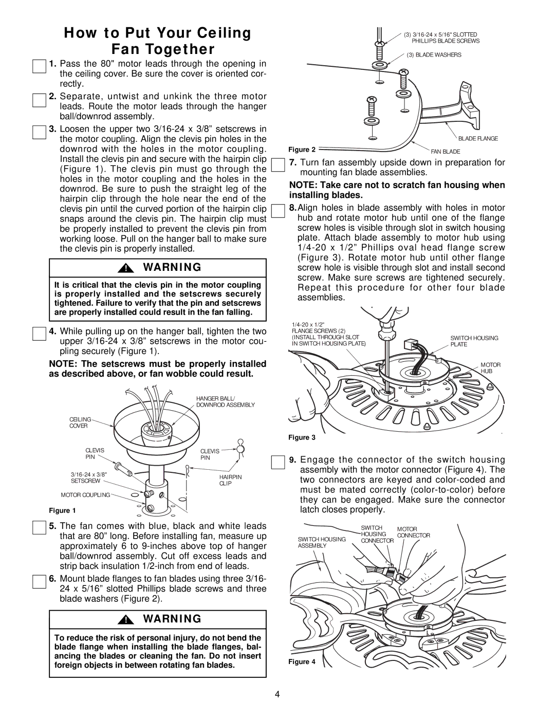
Installation of the CF796 models is designed to be user-friendly. Each fan comes with detailed instructions and includes a comprehensive mounting system, making it accessible for both seasoned DIYers and those new to home improvement projects.
In summary, the Emerson CF796HGMO0, CF796MP0, and CF796CW0 ceiling fans combine stylish aesthetics with robust technology. Their efficient motors, smart connectivity, versatile speed settings, and integrated LED lighting make them an excellent choice for homeowners looking to enhance their comfort and style while being mindful of energy consumption. Whether upgrading an existing space or outfitting a new one, the Emerson CF796 series offers a perfect blend of form and function.