CF875 specifications
The Emerson CF875 is a sophisticated ceiling fan renowned for its blend of style and performance, making it a popular choice for both residential and commercial spaces. Designed with an emphasis on both aesthetics and functionality, this fan enhances the ambiance of any room while providing optimal airflow.One of the standout features of the Emerson CF875 is its elegant design. Available in various finishes, including classic white, brushed steel, and oil-rubbed bronze, it complements a wide range of interior decors, from modern to traditional. The 72-inch blade span ensures that it can efficiently circulate air across large areas, making it ideal for spacious living rooms, master bedrooms, and open-concept spaces.
Equipped with a powerful yet quiet motor, the CF875 operates with minimal noise, even at higher speeds. This is particularly beneficial for those seeking a peaceful indoor environment, whether it’s for sleeping, relaxation, or work. The fan's motor is designed for long-lasting performance and energy efficiency, contributing to lower electricity bills while maintaining comfort.
The Emerson CF875 also features a unique blade pitch that optimizes airflow, ensuring efficient circulation. With the capability to operate in reverse, users can effectively manage air temperature throughout the year. In the summer months, it creates a cool breeze, while in winter, reversing the direction promotes even heat distribution from heating systems.
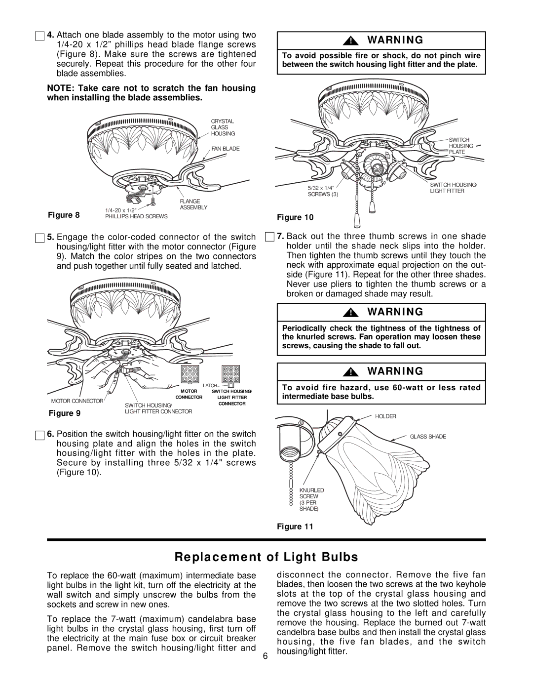
Installation of the CF875 is straightforward, and it is compatible with a range of control options, including wall controls, remote controls, and smart home systems. This level of versatility makes it user-friendly and adaptable to different preferences and setups.
Additionally, the CF875 is constructed with high-quality materials, ensuring durability and long-term satisfaction. The fan’s contemporary design aesthetics combined with its powerful cooling features make it an excellent addition to any space.
In summary, the Emerson CF875 excels in providing a perfect balance of design, efficiency, and functionality, making it a top choice among ceiling fans. Whether you're looking to enhance your home's comfort or improve airflow in a commercial setting, the CF875 delivers reliable performance with a touch of elegance. Its numerous features and advanced technologies truly set it apart in the ceiling fan market.

