INSTALLATION (continued)

handle

shafts

handle


handle


Figure 1-2.

Figure 1-3.

Figure 1-4


150 – 400 A (3 pole)

600 & 800 A (& 4 pole 400 A)

3000 & 4000

A

E–design switches

F–design switches

F–design transfer switches

1 – Manual Operation

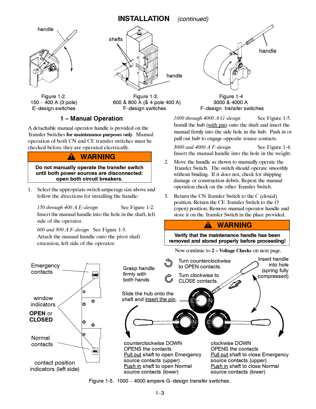
A detachable manual operator handle is provided on the Transfer Switches for maintenance purposes only. Manual operation of both CN and CE transfer switches must be checked before they are operated electrically.

Do not manually operate the transfer switch until both power sources are disconnected: open both circuit breakers.

1.Select the appropriate switch amperage size above and follow the directions for installing the handle:

150 through 400 A E–design See Figure 1-2.

Insert the manual handle into the hole in the shaft, left side of the operator.

600 and 800 A F–design See Figure 1-3. Attach the manual handle onto the pivot shaft extension, left side of the operator.

1000 through 4000 A G–design

See Figure 1-5.

Install the hub (with pin) onto the shaft and insert the manual firmly into the side hole in the hub. Push in or pull out hub to engage opposite source contacts.

3000 and 4000 A F–design See Figure 1-4.

Insert the manual handle into the hole in the weight.

2.Move the handle as shown to manually operate the Transfer Switch. The switch should operate smoothly without binding. If it does not, check for shipping damage or construction debris. Repeat the manual operation check on the other Transfer Switch.

3.Return the CN Transfer Switch to the C (closed) position. Return the CE Transfer Switch to the O (open) position. Remove manual operator handle and store it on the Transfer Switch in the place provided.

Verify that the maintenance handle has been removed and stored properly before proceeding!

Now continue to 2 – Voltage Checks on next page.

Emergency contacts

window

indicators

OPEN or

CLOSED

Grasp handle firmly with both hands

Slide the hub onto the shaft and insert the pin.

Turn counterclockwise

Insert handle

into hole

to OPEN contacts.

(spring fully

Turn clockwise to

compressed)

CLOSE contacts.


Normal contacts

contact position

indicators (left side)

counterclockwise DOWN

clockwise DOWN

OPENS the contacts

OPENS the contacts

Pull out shaft to open Emergency

Pull out shaft to close Emergency

source contacts (upper)

source contacts (upper)

Push in shaft to open Normal

Push in shaft to close Normal

source contacts (lower)

source contacts (lower)

Figure 1-5. 1000 – 4000 ampere G–design transfer switches.

1--3

Page 6
Image 6
Emerson GDESIGN 10004000A, FDESIGN 30004000A, FDESIGN 600800A manual Manual Operation, Closed

FDESIGN 600800A, FDESIGN 30004000A, GDESIGN 10004000A specifications

Emerson's range of products, specifically the GDESIGN 10004000A, FDESIGN 600800A, and FDESIGN 30004000A, showcase the company's commitment to innovation and excellence in design and engineering. Each model presents unique features and technologies tailored to meet the demands of modern industrial applications.

The GDESIGN 10004000A is renowned for its robust performance in automation processes. This model boasts a user-friendly interface complemented by advanced connectivity options, including Ethernet and USB ports, facilitating seamless integration with existing systems. Equipped with intuitive software, it allows operators to configure and monitor the system effortlessly, enhancing productivity. The GDESIGN's high processing speed ensures minimal downtime and efficient task execution, making it a preferred choice for industries requiring precise control and reliability.

On the other hand, the FDESIGN 600800A focuses on energy efficiency and sustainability. This model stands out with its advanced thermal management technology, optimizing heat dissipation while minimizing energy consumption. The FDESIGN 600800A also features a modular design, enabling easy upgrades and maintenance. Its compatibility with various sensors and controllers facilitates comprehensive monitoring of environmental conditions, making it ideal for applications where energy conservation is paramount.

Lastly, the FDESIGN 30004000A integrates cutting-edge automation technologies designed for scalability and flexibility. This model utilizes smart algorithms to enhance operational efficiency, ensuring that processes can adapt to changing production requirements without significant reconfiguration. The FDESIGN 30004000A is also equipped with real-time data analytics capabilities, allowing businesses to make informed decisions based on current system performance. This feature drives continuous improvement and optimization, empowering users to achieve their operational goals effectively.

In summary, Emerson's GDESIGN 10004000A, FDESIGN 600800A, and FDESIGN 30004000A represent the company’s dedication to delivering innovative solutions that cater to diverse industrial demands. Each model's unique features, including advanced connectivity, energy efficiency, and smart automation, position them as exceptional options for organizations seeking reliability and performance in their operations. With a focus on usability and cutting-edge technology, Emerson continues to lead the way in industrial design and engineering.