Linear Power Cover Instruction Manual | Model Number: |
Power Supplies Affected
What’s Included
•Part B Cover
•Two Plastic Screws M3x6 mm
•Two
•Instruction Manual
Assembly Instructions for Cover Installation
M3x6 mm
BCover
Part
FIGURE 1
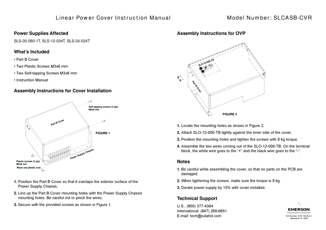
Assembly Instructions for OVP
![]()
![]()
![]() -TB
-TB![]()
![]()
![]()
![]()
![]() SLO
SLO ![]()
![]()
![]()
![]()
![]()
![]()
![]()
![]()
Part
B
![]()
![]() Cover
Cover
FIGURE 2
1. | Locate the mounting holes as shown in Figure 2. |
2. | Attach |
3. | Position the mounting holes and tighten the screws with 8 kg torque. |
4. | Assemble the two wires coming out of the |
![]()
![]() *
*
Plastic screws (2 qty) M3x6 mm
*Must use plastic only
![]()
![]() *
*
Chassis
Supply
Power
block, the white wire goes to the “+” and the black wire goes to the |
Notes
1. Be careful while assembling the cover, so that no parts on the PCB are |
damaged. |
1.Position the Part B Cover so that it overlaps the exterior surface of the Power Supply Chassis.
2.Line up the Part B Cover mounting holes with the Power Supply Chassis mounting holes. Be careful not to pinch the wires.
2. | When tightening the screws, make sure the torque is 8 kg. |
3. | Derate power supply by 15% with cover installed. |
Technical Support
3. Secure with the provided screws as shown in Figure 1. | U.S.: (800) |
| International: (847) |
|
Part Number:
September 22, 2008