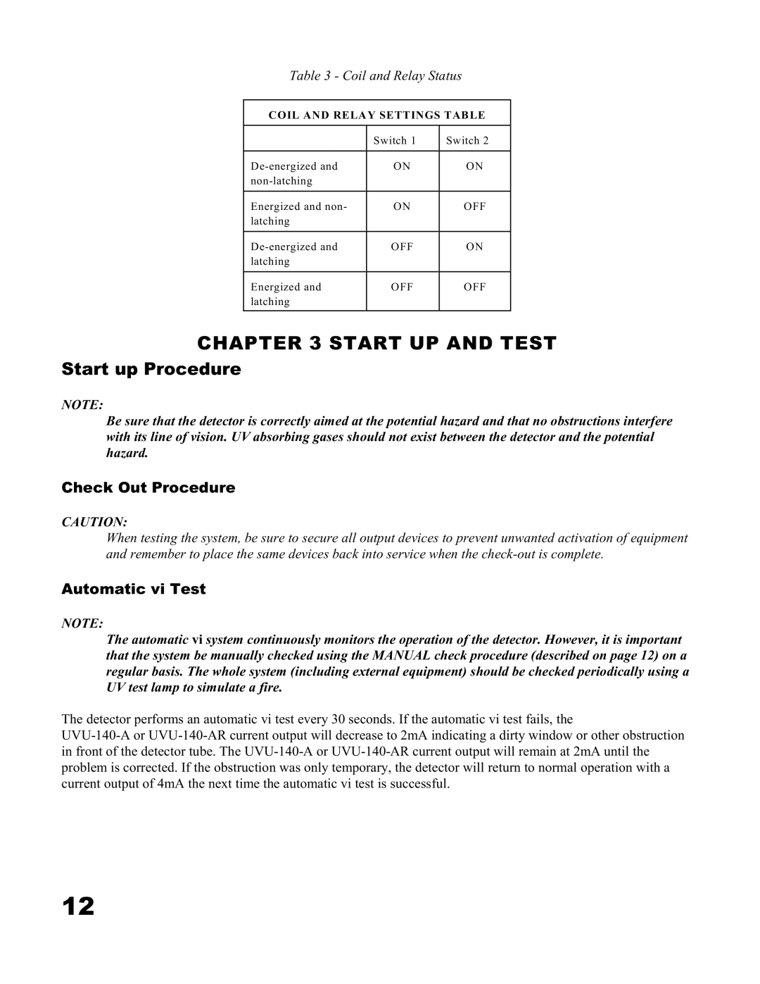
Table 3 - Coil and Relay Status
COIL AND RELAY SETTINGS TABLE
| Switch 1 | Switch 2 |
ON | ON | |
|
| |
Energized and non- | ON | OFF |
latching |
|
|
OFF | ON | |
latching |
|
|
Energized and | OFF | OFF |
latching |
|
|
CHAPTER 3 START UP AND TEST
Start up Procedure
NOTE:
Be sure that the detector is correctly aimed at the potential hazard and that no obstructions interfere with its line of vision. UV absorbing gases should not exist between the detector and the potential hazard.
Check Out Procedure
CAUTION:
When testing the system, be sure to secure all output devices to prevent unwanted activation of equipment and remember to place the same devices back into service when the
Automatic vi Test
NOTE:
The automatic vi system continuously monitors the operation of the detector. However, it is important that the system be manually checked using the MANUAL check procedure (described on page 12) on a regular basis. The whole system (including external equipment) should be checked periodically using a UV test lamp to simulate a fire.
The detector performs an automatic vi test every 30 seconds. If the automatic vi test fails, the
12