GAS SUPPLY

The gas line can be routed either through the floor or wall. The gas line opening should be made at this time. Location of the opening will be determined by the position of floor joists and the valve and union used for servicing.

Gas Supply

Check all local codes for requirements, especially for the size and type of gas supply line required.

Recommended Gas Pipe Diameter

Pipe Length

Schedule 40 Pipe

Tubing, Type L

(Feet)

Inside Diameter

Outside Diameter


Nat.

L.P.

Nat.

L.P.

0-10

1/2"

3/8"

1/2"

3/8"


1.3 cm

1.0 cm

1.3 cm

1.0 cm

10-40

1/2"

1/2"

5/8"

1/2"


1.3 cm

1.3 cm

1.6 cm

1.3 cm

40-100

1/2"

1/2"

3/4"

1/2"


1.3 cm

1.3 cm

1.9 cm

1.3 cm

100-150

3/4"

1/2"

7/8"

3/4"


1.9 cm

1.3 cm

2.2 cm

1.9 cm


Note: Never use plastic pipe. Check to confirm whether your local codes allow copper tubing or galvanized.

Note: Since some municipalities have additional local codes, it is always best to consult your local authority and installation code.

39/16"

(90mm)

1 11/16" (43mm)

TO WALL

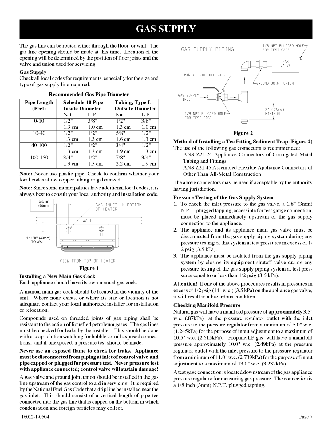
Figure 1

Installing a New Main Gas Cock

Each appliance should have its own manual gas cock.

A manual main gas cock should be located in the vicinity of the unit. Where none exists, or where its size or location is not adequate, contact your local authorized installer for installation or relocation.

Compounds used on threaded joints of gas piping shall be resistant to the action of liquefied petroleum gases. The gas lines must be checked for leaks by the installer. This should be done with a soap solution watching for bubbles on all exposed connec- tions, and if unexposed, a pressure test should be made.

Never use an exposed flame to check for leaks. Appliance must be disconnected from piping at inlet of control valve and pipe capped or plugged for pressure test. Never pressure test with appliance connected; control valve will sustain damage!

A gas valve and ground joint union should be installed in the gas line upstream of the gas control to aid in servicing. It is required by the National Fuel Gas Code that a drip line be installed near the gas inlet. This should consist of a vertical length of pipe tee connected into the gas line that is capped on the bottom in which condensation and foreign particles may collect.

Figure 2

Method of Installing a Tee Fitting Sediment Trap (Figure 2) The use of the following gas connectors is recommended:

ANS Z21.24 Appliance Connectors of Corrugated Metal Tubing and Fittings

ANS Z21.45 Assembled Flexible Appliance Connectors of Other Than All-Metal Construction

The above connectors may be used if acceptable by the authority having jurisdiction.

Pressure Testing of the Gas Supply System

1.To check the inlet pressure to the gas valve, a 1/8" (3mm) N.P.T. plugged tapping, accessible for test gauge connection, must be placed immediately upstream of the gas supply connection to the appliance.

2.The appliance and its appliance main gas valve must be disconnected from the gas supply piping system during any pressure testing of that system at test pressures in excess of 1/ 2 psig (3.5 kPa).

3.The appliance must be isolated from the gas supply piping system by closing its equipment shutoff valve during any pressure testing of the gas supply piping system at test pres- sures equal to or less than 1/2 psig (3.5 kPa).

Attention! If one of the above procedures results in pressures in excess of 1/2 psig (14" w.c.) (3.5 kPa) on the appliance gas valve, it will result in a hazardous condition.

Checking Manifold Pressure

Natural gas will have a manifold pressure of approximately 3.5" w.c. (.87kPa) at the pressure regulator outlet with the inlet pressure to the pressure regulator from a minimum of 5.0" w.c. (1.245kPa) for the purpose of input adjustment to a maximum of 10.5" w.c. (2.615kPa). Propane/LP gas will have a manifold pressure approximately 10.0" w.c. (2.49kPa) at the pressure regulator outlet with the inlet pressure to the pressure regulator from a minimum of 11.0" w.c. (2.739kPa) for the purpose of input adjustment to a maximum of 13.0" w.c. (3.237kPa).

A test gage connection is located downstream of the gas appliance pressure regulator for measuring gas pressure. The connection is a 1/8 inch (3mm) N.P.T. plugged tapping.

16012-1-0504

Page 7

Page 7
Image 7
Empire Products BF-30-2, BF-20-2 GAS Supply, Installing a New Main Gas Cock, Pressure Testing of the Gas Supply System

BF-30-2, BF-20-2, BF-10-2 specifications

Empire Products has established itself as a notable player in the realm of industrial solutions with its comprehensive range of BF series products, particularly the BF-30-2, BF-10-2, and BF-20-2. These models, each designed to meet various operational needs, exhibit the company’s commitment to innovation and efficiency.

The BF-30-2 is the flagship model in the series, equipped with advanced features that cater to heavy-duty applications. It boasts a robust design coupled with high-performance capabilities. One of its standout technologies includes an efficient energy management system that optimizes power consumption without compromising performance. This model also features a user-friendly interface for easy operation and monitoring, ensuring that users can quickly adapt to its functionalities. The BF-30-2 is particularly well-suited for applications requiring precision and high throughput, making it a favorite among manufacturers looking for reliability and efficiency.

Next in the lineup is the BF-20-2, which strikes a balance between power and versatility. This model is designed to handle moderate to intense workloads, making it ideal for businesses that require adaptability in their operations. It is equipped with adaptive technology that allows it to adjust its performance based on real-time operational demands. The BF-20-2 also offers enhanced safety features, ensuring that operators can work confidently and comfortably.

The BF-10-2, while smaller in capacity, should not be underestimated. It is engineered for small to medium-sized tasks, perfect for businesses that require compact solutions without sacrificing quality. This model incorporates cutting-edge materials and components designed to maximize durability and reduce maintenance needs. Additionally, the BF-10-2 is highly energy-efficient, making it an excellent choice for environmentally conscious companies looking to minimize their carbon footprint.

All three models share a few key characteristics that highlight the essence of Empire Products' engineering prowess. They are designed for easy integration into existing systems, which simplifies upgrades for businesses looking to enhance their operational capabilities. Moreover, their modular design allows for customizable configurations, catering to specific user requirements.

In conclusion, the Empire Products BF series, encompassing the BF-30-2, BF-20-2, and BF-10-2, represents the synergy of performance, innovation, and versatility. Each model serves a unique purpose, allowing businesses to select the perfect equipment to meet their operational goals while benefiting from the latest technological advancements in the industry.