OPTIONAL BLOWER INSTALLATION INSTRUCTIONS
Models
Direct Vent Wall Furnaces
Installing Optional
1.For
1.For
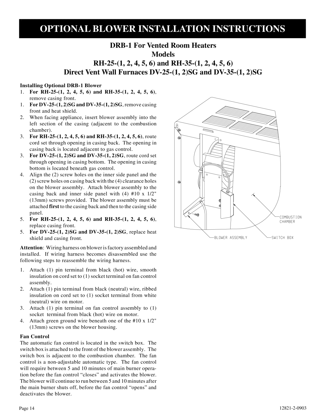
2. When facing appliance, insert blower assembly into the left section of the casing (adjacent to the combustion chamber).
3.For RH-25-(1, 2, 4, 5, 6) and RH-35-(1, 2, 4, 5, 6), route
cord set through opening in casing back. The opening in casing back is located adjacent to gas control.
3.For
4.Align the (2) screw holes on the inner side panel and the
(2) screw holes on casing back with the (4) clearance holes on the blower assembly. Attach blower assembly to the casing back and inner side panel with (4) #10 x 1/2" (13mm) screws provided. The blower assembly must be attached first to the casing back and then to the casing side panel.
5. For RH-25-(1, 2, 4, 5, 6) and RH-35-(1, 2, 4, 5, 6),
replace casing front.
5.For DV-25-(1, 2)SG and DV-35-(1, 2)SG, replace heat
shield and casing front.
Attention: Wiring harness on blower is factory assembled and installed. If wiring harness becomes disassembled use the following steps to reassemble the wiring harness.
1.Attach (1) pin terminal from black (hot) wire, smooth insulation on cord set to (1) socket terminal on fan control assembly.
2.Attach (1) pin terminal from black (neutral) wire, ribbed insulation on cord set to (1) socket terminal from white (neutral) wire on motor.
3.Attach (1) pin terminal on fan control assembly to (1) socket terminal from black (hot) wire on motor.
4.Attach green ground wire beneath one of the #10 x 1/2" (13mm) screws on the blower housing.
Fan Control
The automatic fan control is located in the switch box. The switch box is attached to the front of the blower assembly. The switch box is adjacent to the combustion chamber. The fan control is a
Page 14 |