GSM/GPRS Spider SA User Manual
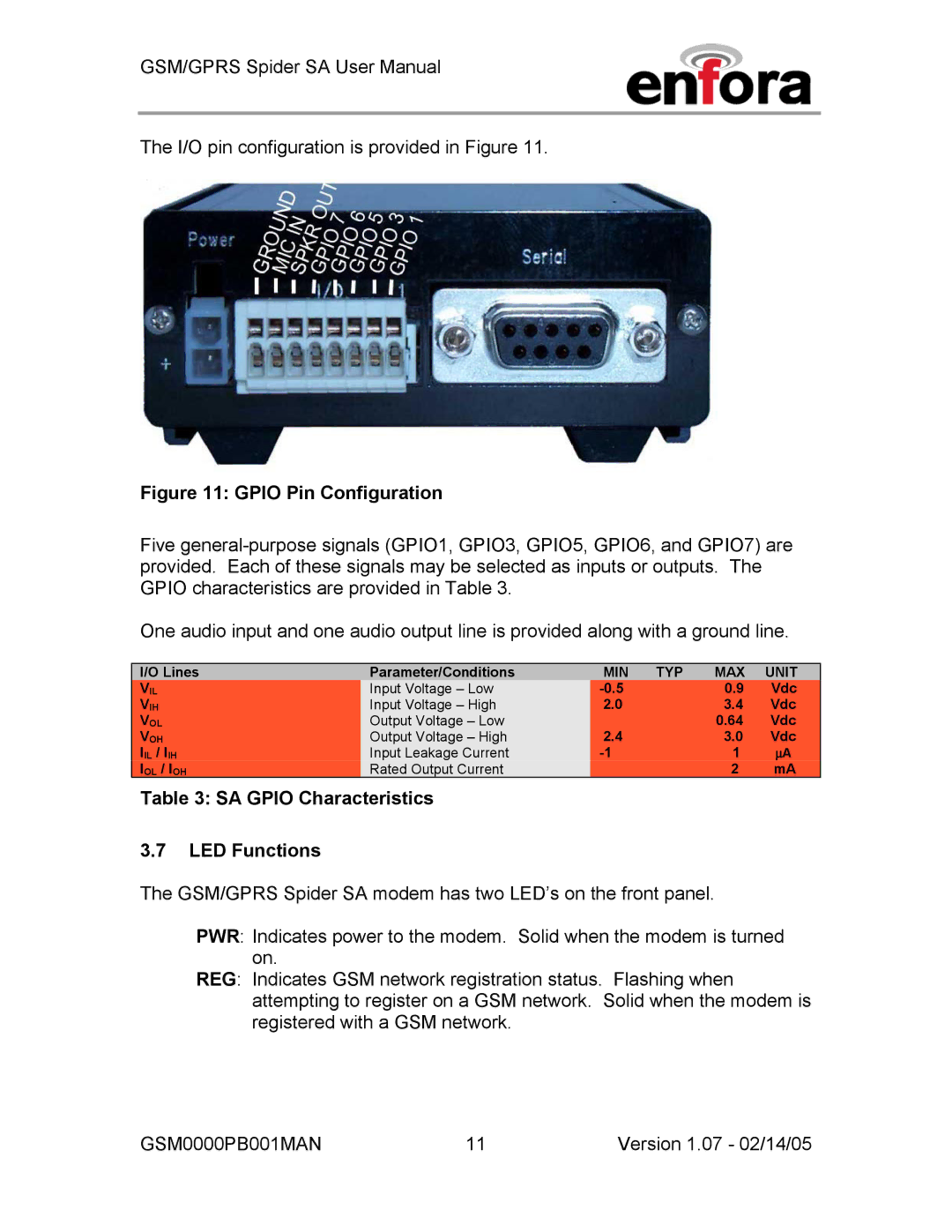
The I/O pin configuration is provided in Figure 11.
Figure 11: GPIO Pin Configuration
Five
One audio input and one audio output line is provided along with a ground line.
I/O Lines | Parameter/Conditions | MIN | TYP | MAX | UNIT |
VIL | Input Voltage – Low |
| 0.9 | Vdc | |
VIH | Input Voltage – High | 2.0 |
| 3.4 | Vdc |
VOL | Output Voltage – Low |
|
| 0.64 | Vdc |
VOH | Output Voltage – High | 2.4 |
| 3.0 | Vdc |
IIL / IIH | Input Leakage Current |
| 1 | ∝A | |
IOL / IOH | Rated Output Current |
|
| 2 | mA |
Table 3: SA GPIO Characteristics
3.7LED Functions
The GSM/GPRS Spider SA modem has two LED’s on the front panel.
PWR: Indicates power to the modem. Solid when the modem is turned on.
REG: Indicates GSM network registration status. Flashing when attempting to register on a GSM network. Solid when the modem is registered with a GSM network.
GSM0000PB001MAN | 11 | Version 1.07 - 02/14/05 |
