GSM2218PB001MAN - GSM/GPRS MT-GL User Manual Page 16
Copyright 2005, Enfora L.P
2.7 Connecting the Power Source
The GSM/GPRS MT-GL has an input voltage range of 9 – 30 V DC. (See Table 3 and Table 4). The
power and ignition pins can support 9 – 30 V DC input voltage. The user has an option to connect
these wires depending on the desired functionality. Described below are the desired functionality and
their associated wire connecting procedure:
!
Use of the device outside of the specified voltage range may result in damage to the device and/or undesirable results. !
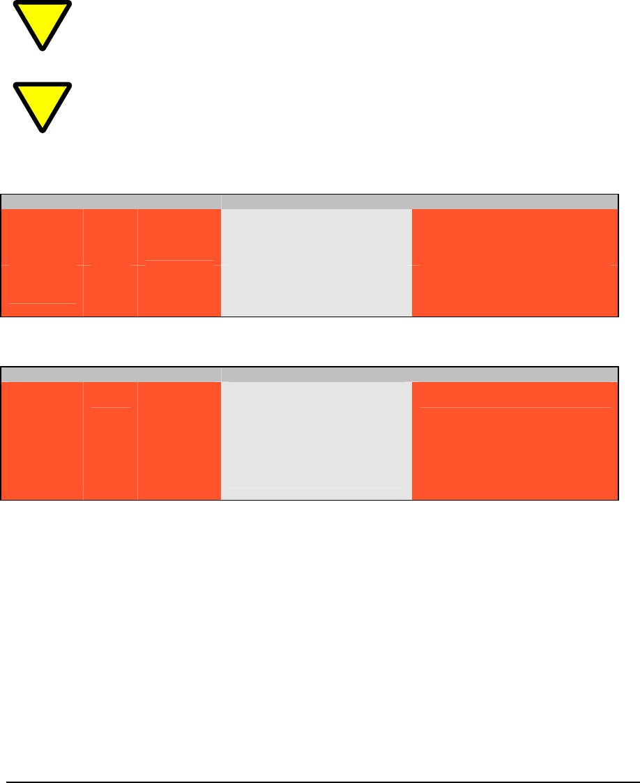
Please follow the specifications as listed in the table below. Enfora is not liable for damage to the MT-GL caused due to user error. PRELIMINARY TABLES
Enfora MT-G (@ 12 Volts) Average Current (mAmps) Peak Current (Amps)
GSM 850 &
900
GSM
1TX/1RX
1RX
Idle
390 mA
180 mA
65
0.600@32.5
DCS 1800 &
PCS 1900
GSM
1TX/1RX
1RX
Idle
400 mA
190 mA
55 mA
0.570@32.0
Table 3 - GSM Operating Power
Enfora MT-G (@ 12 Volts) Average Current (mAmps) Peak Current (Amps)
GSM 850 &
900
GPRS
TBD1TX/1RX
1RX
Idle
400 mA
190 mA
55 mA
0.590@32.0
DCS 1800 &
PCS 1900
GPRS
TBD
400 mA
200 mA
55 mA
0.560@31.5
Table 4 - GPRS Operating Power
• MT-GL Always ON
o Connect the power and ground wires of the MT-GL to the battery leads. The MT-GL
will always remain ON as long as the battery lasts.
o The MT-GL will be non-operational when the input voltage and current requirements
are not met (battery drains).
o The Ignition wire has to be left open (not connected).
• MT-GL Turns Off when Ignition Turned Off
o Connect the power line of the MT-GL to an auxiliary power source, i.e. ignition.
o Connect the ground wire to the chassis or negative terminal of the battery
o The Ignition wire has to be left open (not connected).