Connecting Switches to the RPS 2
Desktop or Shelf Mounting
1.Attach the four adhesive feet to the bottom of the first RPS unit.
Figure 2-3. Attaching the Adhesive Feet
2.Set the device on a flat surface near an AC power source, making sure there are at least two inches of space on all sides for proper air flow.
Connecting Switches to the RPS
Caution: DO NOT connect the RPS to an AC power source until DC power cords have been connected to the supported switches.
To connect switches to the RPS, refer to Figure
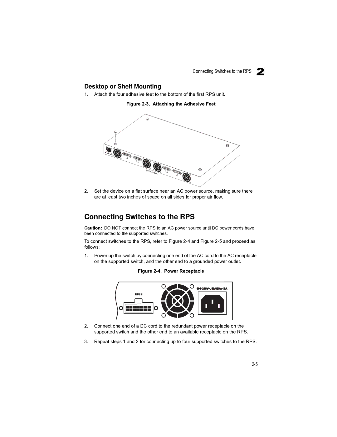
1.Power up the switch by connecting one end of the AC cord to the AC receptacle on the supported switch, and the other end to a grounded power outlet.
Figure 2-4. Power Receptacle
2.Connect one end of a DC cord to the redundant power receptacle on the supported switch and the other end to an available receptacle on the RPS.
3.Repeat steps 1 and 2 for connecting up to four supported switches to the RPS.