When planning your installation, it will be necessary to select the proper length of vent pipe for your particular requirements. It is important to note when passing through a wall, the maximum allowable wall thickness is 10-inches (254mm), 1 ½ inches clearance to combustibles must be maintained. Select the amount of vertical rise desired for “vertical-to-horizontal” type installations. To determine the length of vent pipe required for vertical installations, measure the distance from the appliance flue outlet to the ceiling, the ceiling thickness, the vertical rise through the attic or second story, and allow for sufficient vent height above the roofline. For two story applications, A firestop is required at each floor level. If an offset is needed in the attic, additional pipe and elbows will be required. To connect the venting system to the appliance flue outlet, a twist-lock adapter is built into the appliance at the factory.

HORIZONTAL INSTALLATION

STEP 1. Set the appliance in the desired location. Check to determine if wall studs or roof rafters are in the way when the venting system is attached. If this is the case, you may want to adjust the location of the appliance.

STEP 2. Direct vent pipe and fittings are designed with special twist-lock connections. Assemble the desired combination of black pipe and elbows to the appliance adapter with pipe seams oriented towards the wall or floor, as much out of view as possible.

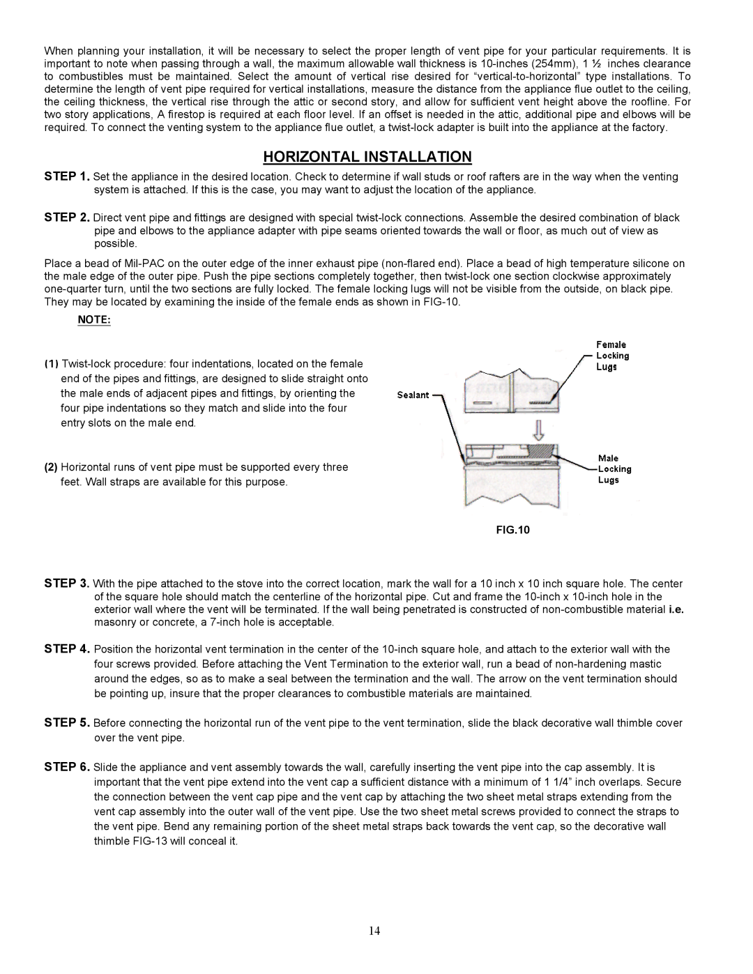
Place a bead of Mil-PAC on the outer edge of the inner exhaust pipe (non-flared end). Place a bead of high temperature silicone on the male edge of the outer pipe. Push the pipe sections completely together, then twist-lock one section clockwise approximately one-quarter turn, until the two sections are fully locked. The female locking lugs will not be visible from the outside, on black pipe. They may be located by examining the inside of the female ends as shown in FIG-10.

NOTE:

(1)Twist-lock procedure: four indentations, located on the female end of the pipes and fittings, are designed to slide straight onto the male ends of adjacent pipes and fittings, by orienting the four pipe indentations so they match and slide into the four entry slots on the male end.

(2)Horizontal runs of vent pipe must be supported every three feet. Wall straps are available for this purpose.

FIG. 10

FIG.10

STEP 3. With the pipe attached to the stove into the correct location, mark the wall for a 10 inch x 10 inch square hole. The center of the square hole should match the centerline of the horizontal pipe. Cut and frame the 10-inch x 10-inch hole in the exterior wall where the vent will be terminated. If the wall being penetrated is constructed of non-combustible material i.e. masonry or concrete, a 7-inch hole is acceptable.

STEP 4. Position the horizontal vent termination in the center of the 10-inch square hole, and attach to the exterior wall with the four screws provided. Before attaching the Vent Termination to the exterior wall, run a bead of non-hardening mastic around the edges, so as to make a seal between the termination and the wall. The arrow on the vent termination should be pointing up, insure that the proper clearances to combustible materials are maintained.

STEP 5. Before connecting the horizontal run of the vent pipe to the vent termination, slide the black decorative wall thimble cover over the vent pipe.

STEP 6. Slide the appliance and vent assembly towards the wall, carefully inserting the vent pipe into the cap assembly. It is important that the vent pipe extend into the vent cap a sufficient distance with a minimum of 1 1/4” inch overlaps. Secure the connection between the vent cap pipe and the vent cap by attaching the two sheet metal straps extending from the vent cap assembly into the outer wall of the vent pipe. Use the two sheet metal screws provided to connect the straps to the vent pipe. Bend any remaining portion of the sheet metal straps back towards the vent cap, so the decorative wall thimble FIG-13 will conceal it.

14

Page 14
Image 14
Enviro 828 DV.FS, 828 MH, 828 DV.INS owner manual Horizontal Installation

828 MH, 828 DV.FS, 828 DV.INS specifications

The Enviro 828 series, including the 828 DV.INS, 828 DV.FS, and 828 MH models, represents a breakthrough in environmental technology, catering to both residential and commercial needs. These innovative systems are designed for efficiency, sustainability, and advanced functionality, making them suitable for various applications.

One of the standout features of the Enviro 828 series is its dual variable input system (DV.INS and DV.FS), which allows users to customize their energy consumption based on real-time demands. This technology not only optimizes performance but also enhances energy efficiency, leading to significant cost savings on utility bills. The adaptive modulation feature intelligently adjusts the output based on workload, ensuring that the system operates only as needed.

Another hallmark of the Enviro 828 series is its commitment to eco-friendliness. Incorporating state-of-the-art filtration technology, these units minimize emissions and reduce carbon footprints. They are equipped with high-efficiency particulate air (HEPA) filters, which are designed to capture even the smallest airborne particles, making them ideal for environments where air quality is a priority.

The 828 MH model further distinguishes itself with its multi-zone capabilities, allowing for distinct heating and cooling settings across different areas of a building. This feature is particularly beneficial in larger homes or office spaces, where temperature preferences may vary significantly from one room to another. Users can enjoy personalized comfort while maintaining overall energy efficiency.

Moreover, the Enviro 828 series employs advanced connectivity options, including smart home integration. Users can monitor and control their systems remotely through mobile applications, enabling real-time adjustments and stats tracking. This connectivity feature not only enhances user convenience but also allows for predictive maintenance alerts, ensuring longevity and operational reliability.

In summary, the Enviro 828 DV.INS, 828 DV.FS, and 828 MH models offer a perfect blend of efficiency, customization, and environmental consciousness. With their innovative technologies, such as dual variable input systems, advanced filtration, multi-zone capabilities, and smart connectivity, these units stand out as top choices for those seeking sustainable solutions in heating and cooling systems. Investing in an Enviro 828 model empowers users to prioritize comfort, efficiency, and environmental stewardship.