stylus Coiaf ~mnwl
Op8fsthg Pfincipks
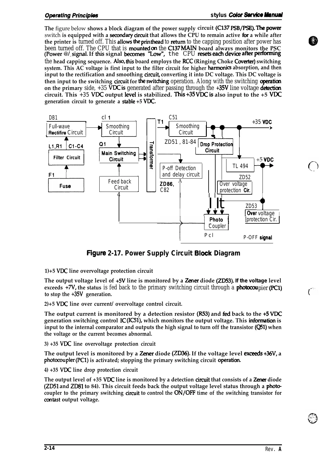
The figure below shows a block diagram of the power supply circuit (C137 PSB/PSE). The POW=
switch is equipped with a semndary *it that allows the CPU to remain active fbr a while after
the printer is turned off. This allows the printkad to return to the capping position after power has
been turned off. The CPU that is rnowted CXI the C137 MAIN board always monitors the PSC
(Power @/ ~ sipl. If w signal bemmes ‘ZOW”, the CPU resets -* device * -g
the head capping sequence. Nw, this board employs the RCC (Ringing Choke Coverter) switching
system. This AC voltage is first input to the filter circuit for higher harmoni cs absorption, and then
input to the rectification and smoothing arcuit, converting it into DC voltage. This DC voltage is
then input to the switching arcuit for the swittig operation. Along with the switching operatim
on the primary side, +35 WC is generated after passing through the +35V line voltage detectim
circuit. This +35 VDC output level is stabilized. This +3S VDC is also input to the +5 VDC
generation circuit to generate a stable +5 VDC.
DB1
1
Full-wave
Rectifire Circuit I
L
A
W-@
Filter Circuit
d
F1
Fuse
cl 1
1
r T1
b Smoothing
Circuit
—-T----1
F+13
I
7
Feed back
Circuit
4
)
C51
Smoothing
Circuit
+35 Voc
*
➤
ZD51 , 81-84 ~~
‘ +5 VDC
TL 494
P-off Detection
and delay circuit
ZD86,
C82
ZD52
Over voltage
protection Cir.
A
I
I 1’”1
I It
I
~
I
[
‘hot? I
4
I
ZD53 ,
[Over voltage I
[protection Cir. [
Coupler I
Pcl
P-OFF signal
Hgure 2-17. Power Supply Circuit Biock Diagram
1)+5 VDC line overvoltage protection circuit
The output voltage level of +5V line is monitored by a Zener diode (ZD53). If the voltage level
exceeds +7V, the status is fed back to the primary switching circuit through a photocou pier (-WI)
to stop the +35V generation.
2)+5 VDC line over current/ overvoltage control circuit.
The output current is monitored by a detection resistor (R53) and M back to the +5 VDC
generation switching control IC (IC51), which monitors the output voltage. This inhmation is
input to the internal comparator and outputs the high signal to turn off the transistor (QW) when
the voltage or the current becomes abnormal.
3) +35 VDC line overvoltage protection circuit
The output level is monitored by a Zener diode (ZD36). If the voltage level excwds +36V, a
photocoupler (PCl) is activated; stopping the primary switching circuit operatim.
4) +35 VDC line drop protection circuit
The output level of +35 VDC line is monitored by a detection arcuit that consists of a Zener diode
(ZD51 and ZD81 to 84). This circuit feeds back the output voltage level status through a photm
coupler to the primary switching arcuit to control the ON/OPP time of the switching transistor for
contast output voltage.
2-14
Rev. A