Sty/w Color Servke Manual
Opwating Pr’inc@es
2.3.2.7 D-RAM Refreshment Controller
The H8 CPU is eauimxd with a the refresh controller into the internal mntroller. This CPU can
contact the 16-bit ien’~ IC5 D-RAM which is a 2 CAS type. The fallowing table lists the
method between the H8 CPU and the 2 CAS BRAM.
Table 2-10. Junction Method (CPU-2CAS DRAM)
CPU
2 CAS D-RAM
HWR
UCAS
im
LCAS
CS3
m
m
m
*
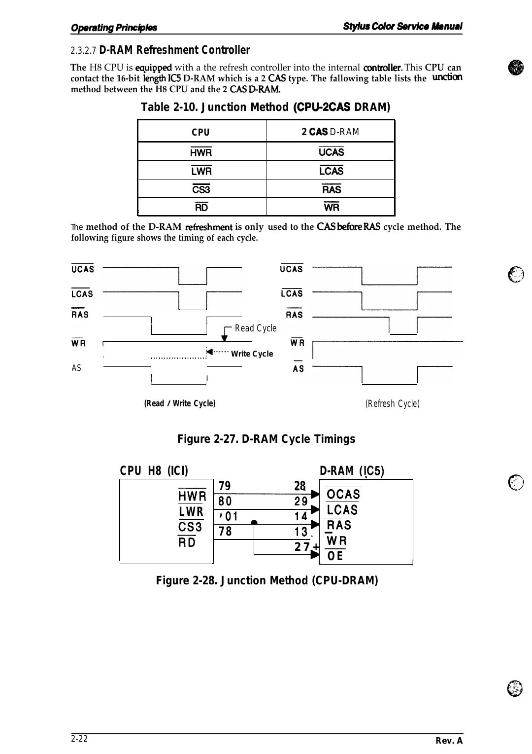
The method of the D-RAM reikeshment is only used to the CAS befbre RAS cycle method. The
following figure shows the timing of each cycle.
UCAS
LCAS
L
,
I
I
I I
Read Cycle
*-””--” Write Cycle
. . . . . . . . . . . . . . . . . . . . . .
1
AS
I 1
I
J
(Read / Write Cycle)
(Refresh Cycle)
Figure 2-27. D-RAM Cycle Timings
D-RAM (IC5)
79
“ “
28
OCAS
HWR ~
80
LCAS
LWR , ~,
14F
&
RAS
=3 7 8
13b —
RD
27+ M
+ 1 O E
CPU H8 (ICI)
I
J
J
Figure 2-28. Junction Method (CPU-DRAM)
2-22
Rev. A