StyhJs Color Service Manual
Adjustments
1. Connect the PC to the target printer and turn the printer on.
2. Execute BASIC on the PC and run the program “VERXXX.BAS”.
( “
1. Destination Setting
2. Head Angle Confmnation Pattern Printing
(Head Front/Rear Vertical Position Printing)
3. Head Front/Rear Vertical Position Confirmation
4. Head Gap Adjustment
5. Bi-D Adjustment
6. Internal Timer Reset
7. END
3. When the main menu appears, choose “Head Angle Confirmation Pattern Printing” by
entering “2” from the keyboard. (The printer prints the check pattern with a sample name. )
■ When replacing both the blackhead and the color head, always adjust the color head angle
first. The black head angle is based upon thecolorhead angle.
N A@er you replace the blackhead and ~“nt the black head angle pattern, you only have to
insert the angular spacer if the pattern is incorrect.
,
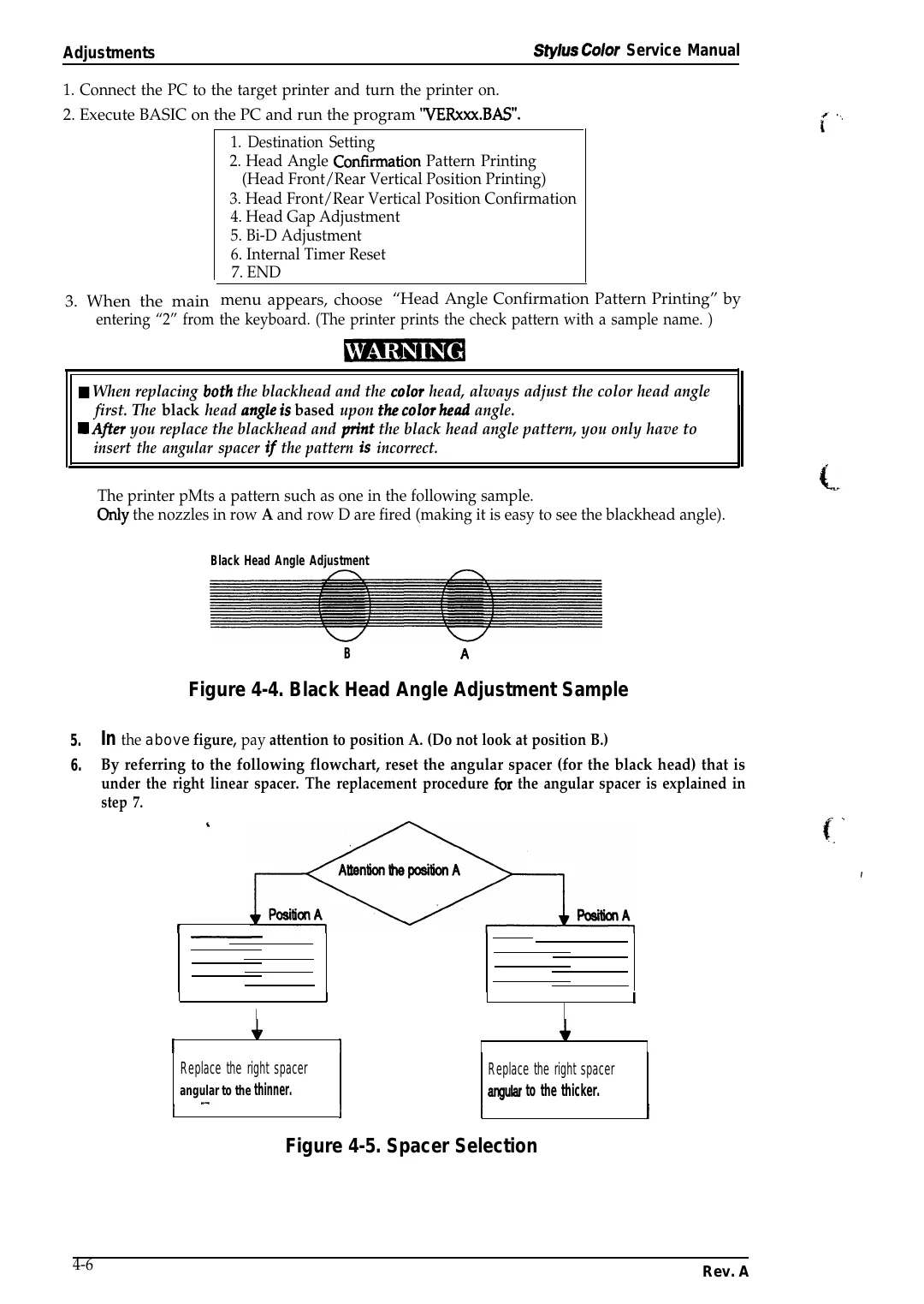
The printer pMts a pattern such as one in the following sample.
Only the nozzles in row A and row D are fired (making it is easy to see the blackhead angle).
L
Black Head Angle Adjustment
B
A
Figure 4-4. Black Head Angle Adjustment Sample
5.
6.
In the above figure, pay attention to position A. (Do not look at position B.)
By referring to the following flowchart, reset the angular spacer (for the black head) that is
under the right linear spacer. The replacement procedure fOr the angular spacer is explained in
step 7.
4
- - .
f.
I
r
I
I
1
I
I
1
Replace the right spacer
.-
I
I
I
Replace the right spacer
anguk to the thicker.
angular to the thinner.
1
I
J
I
I
Figure 4-5. Spacer Selection
4-6
Rev. A