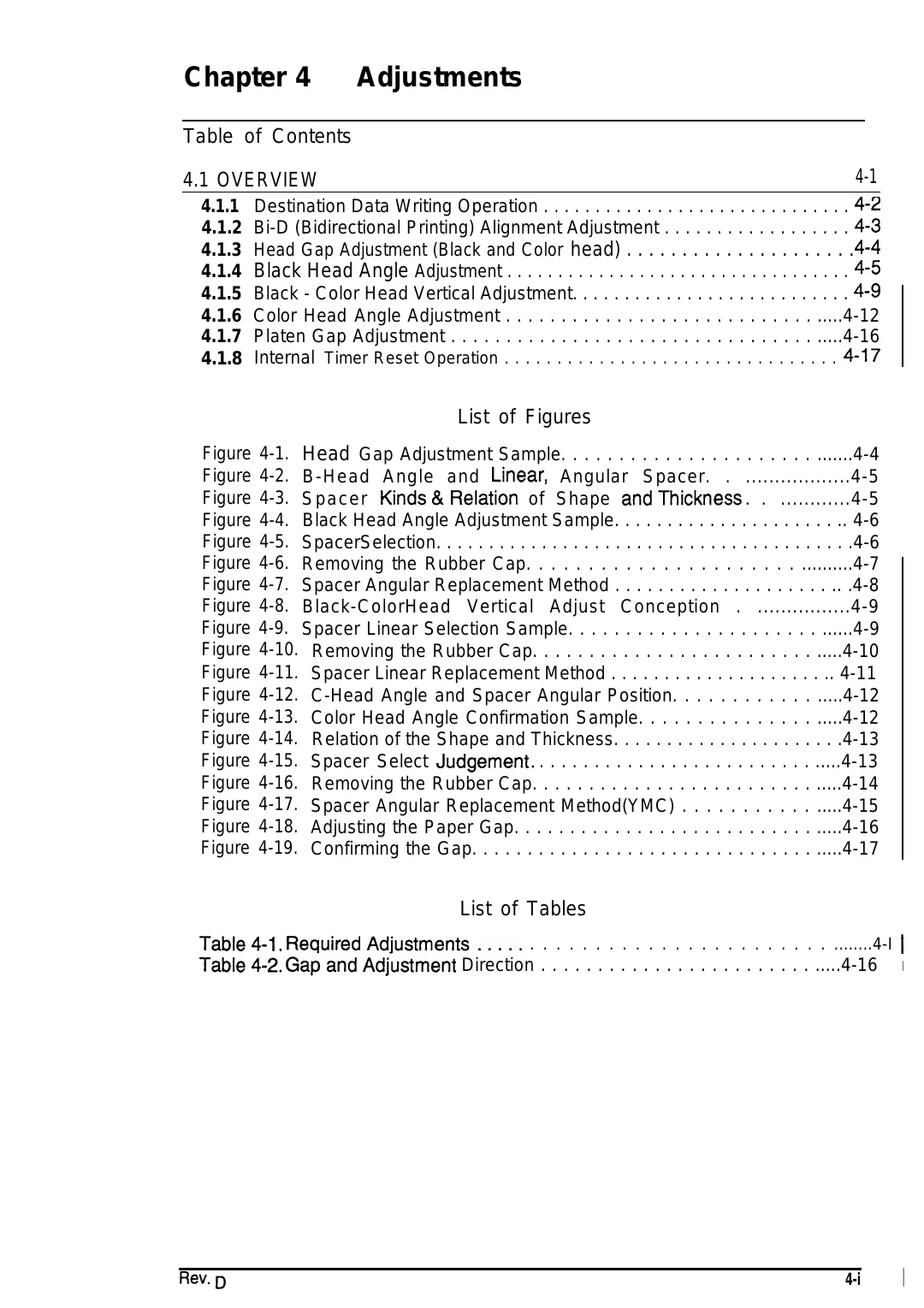
Chapter 4
Adjustments
Table of Contents
4-1
4.1 OVERVIEW
4.1.1 Destination Data Writing Operation . . . . . . . . . . . . . . . . . . . . . . . . . . . . . . Q-z
4.1.2 Bi-D (Bidirectional Printing) Alignment Adjustment . . . . . . . . . . . . . . . . . . fbs
4.1.3 Head Gap Adjustment (Black and Color head) . . . . . . . . . . . . . . . . . . . . . x-x
4.1.4 Black Head Angle Adjustment . . . . . . . . . . . . . . . . . . . . . . . . . . . . . . . . . . x-s
4.1.5 Black - Color Head Vertical Adjustment. . . . . . . . . . . . . . . . . . . . . . . . . . . d-g
4.1.6 Color Head Angle Adjustment . . . . . . . . . . . . . . . . . . . . . . . . . . . . .....4-12
4.1.7 Platen Gap Adjustment . . . . . . . . . . . . . . . . . . . . . . . . . . . . . . . . . .....4-16
4.1.8 Internal Timer Reset Operation . . . . . . . . . . . . . . . . . . . . . . . . . . . . . . . . X-IT
List of Figures
Figure 4-1. Head Gap Adjustment Sample. . . . . . . . . . . . . . . . . . . . . . .......4-4
Figure 4-2. B-Head Angle and LineaC Angular Spacer. . ..................4-5
Figure 4-3. Spacer Kinds&Relation of Shape andThickness. . ............4-5
Figure 4-4. Black Head Angle Adjustment Sample. . . . . . . . . . . . . . . . . . . . . .. 4-6
Figure 4-5. SpacerSelection. . . . . . . . . . . . . . . . . . . . . . . . . . . . . . . . . . . . . . . .4-6
Figure 4-6. Removing the Rubber Cap. . . . . . . . . . . . . . . . . . . . . . ..........4-7
Figure 4-7. Spacer Angular Replacement Method . . . . . . . . . . . . . . . . . . . . .. .4-8
Figure 4-8. Black-ColorHead Vertical Adjust Conception . ................4-9
Figure 4-9. Spacer Linear Selection Sample. . . . . . . . . . . . . . . . . . . . . . ......4-9
Figure 4-10. Removing the Rubber Cap. . . . . . . . . . . . . . . . . . . . . . . . . .....4-10
Figure 4-11. Spacer Linear Replacement Method . . . . . . . . . . . . . . . . . . . . .. 4-11
Figure 4-12. C-Head Angle and Spacer Angular Position. . . . . . . . . . . . .....4-12
Figure 4-13. Color Head Angle Confirmation Sample. . . . . . . . . . . . . . . .....4-12
Figure 4-14. Relation of the Shape and Thickness. . . . . . . . . . . . . . . . . . . . . .4-13
Figure 4-15. Spacer Select Judgement. . . . . . . . . . . . . . . . . . . . . . . . . . .....4-13
Figure 4-16. Removing the Rubber Cap. . . . . . . . . . . . . . . . . . . . . . . . . .....4-14
Figure 4-17. Spacer Angular Replacement Method(YMC) . . . . . . . . . . . .....4-15
Figure 4-18. Adjusting the Paper Gap. . . . . . . . . . . . . . . . . . . . . . . . . . . .....4-16
Figure 4-19. Confirming the Gap. . . . . . . . . . . . . . . . . . . . . . . . . . . . . . . .....4-17
List of Tables
Table4-1. ReqUiredAdjUStrnentS..... . . . . . . . . . . . . . . . . . . . . . . . ........4-I I
Table4-2. GapandAd~ustment Direction . . . . . . . . . . . . . . . . . . . . . . . . .....4-16 I
Fk?V.D
4-i
I