Guide D’UTILISATION Manual DE Instrucciones
Dewalt
General Safety Rules For All Tools
Electrical Safety
Work Area
Service
Additional Specific Safety Instructions for Grinders
Personal Safety
Tool USE and Care
Always Wear EYE Protection When Using this Tool
POWER-OFF Overload Protection
Features
Switch Protection
Clutch D28140, D28144, D28144N
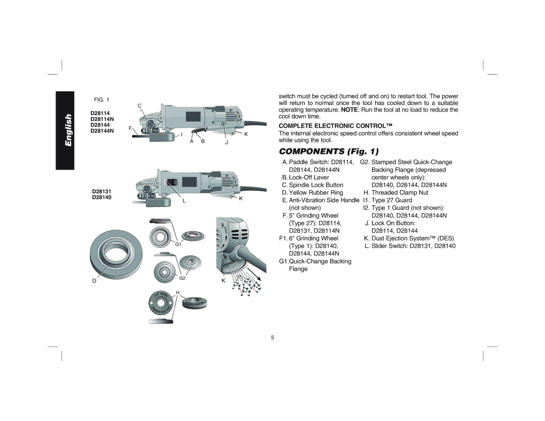
Components Fig
Complete Electronic Control
Rotating the Gear Case
Assembly and Adjustments
2 and 5 Grinding Wheels
Attaching Side Handle
Wire Wheels
Sanding Discs
2and 5 Sanding Flap Discs Accessories
Mounting Guard
Mounting and Removing Guard
Paddle Switch D28114, D28114N, D28144, D28144N
Switches
Soft Start Feature
Operation
LOCK-ON Button D28114, D28144
Slider Switch D28131, D28140
Spindle Lock
Mounting and Removing Hubbed Wheels
Mounting NON-HUBBED Wheels
Surface Grinding with Grinding Wheels
Edge Grinding with Grinding Wheels
Using Sanding Backing Pads
Surface Finishing with Sanding Flap Discs
Mounting Sanding Backing Pads
Mounting and Using Wire Brushes and Wire Wheels
Mounting Wire Brushes and Wire Wheels
Using Wire CUP Brushes and Wire Wheels
Mounting and Using Cutting Type 1 Wheels
Mounting Closed Type 1 Guard
Mounting Cutting Wheels
Accessories Three Year Limited Warranty
Maintenance
Cleaning
Lubrication
Year Free Service
DAY Money Back Guarantee
Règles de sécurité Généralités
Aire DE Travail
Mesures DE Sécurité Électricité
Calibre minimal des cordons de rallonge Tension
Sécurité Personnelle
Utilisation ET Entretien DE L’OUTIL
Entretien
Causes de l’effet de rebond et prévention par l’opérateur
Embrayage Modèles D28140, D28144 ET D28144N
Composant E-SWITCH Protection Protection E-SWITCH
Caractéristiques
Dispositif E-CLUTCH
Composants fig
Fonction Complete Electronic Control
Disques de Ponçage
Meules de 114,3 mm et de 127 mm 4-1/2 et 5 po
Brosses métalliques à touret
Accessoires
Assemblage ET Réglages
Assemblage DE LA Poignée Latérale
Capots protecteurs et brides
Assemblage du capot protecteur
Fonctionnement
Montage ET Démontage DU Capot Protecteur
Modèles D28114, D28114N, D28144 ET D28144N
Interrupteurs
Contacteur À Palette
Fonction DE Démarrage Souple
Dispositif DE Verrouillage DE LA Broche
Bouton DE Verrouillage
Modèles D28114 ET D28144
Assemblage ET Retrait DES Meules À Moyeu Intégré
Meulage DE Surface Avec DES Meules Abrasives
Meule DE 3,31 MM
Meulage DE Chant Avec DES Meules Abrasives
Finition DE Surface Avec DES Disques DE Ponçage Lamelles
Assemblage DES Tampons Pour LE Ponçage
Assemblage et utilisation des brosses métalliques
Utilisation DES Tampons Pour LE Ponçage
Assemblage et utilisation de disques de Type 1 coupe
Assemblage DE Brosses Coniques ET DE BROSSES-BOISSEAU
Utilisation DE Brosses Coniques ET DE BROSSES-BOISSEAU
Assemblage DU Capot Protecteur Fermé Type
Assemblage DE Disques DE Coupe
Utilisation DE Disques DE Coupe
Lubrification
Entretien
Nettoyage
Réparations
Contrat D’ENTRETIEN Gratuit D’UN AN
Garantie DE Remboursement DE 90 Jours
Instrucciones de seguridad generales
Área DE Trabajo
Seguridad Eléctrica
Amperaje
Calibre mínimo para cordones de extensión
Volts Longitud total del cordón en metros
Seguridad Personal
Servicio
Causas del retroceso y su prevención por parte del operador
Protección Contra Sobrecarga POWER-OFF
Características
Embrague D28140, D28144, D28144N
Componentes Fig
DES
Accesorios
Ensamblado Y Ajustes
Rotación de la caja de engranajes
Protector de montaje
Con el cerrojo del protector abierto, gire
Discos de corte de 114,3 mm 2 y 127 mm
Discos de alambre
Discos de lijar
Protectores y bridas
Discos de lijar de 114,3 mm 4-1/2 y 127 mm
Funcionamiento
Interruptores
Interruptor Deslizante D28131, D28140
Función DE Arranque Suave
Interruptor DE Paleta D28114, D28114N, D28144, D28144N
Botón DE Bloqueo D28114, D28144
Montaje Y Extracción DE Discos CON Cubo
Montaje DE Discos SIN Cubo
Esmerilado DE Superficie CON Discos DE Esmerilar
Esmerilado DE Bordes CON Discos DE Esmerilar
Acabado DE Superficies CON Discos DE Lijar
Montaje DE LAS Almohadillas DE Respaldo Para Lijar
USO DE Almohadillas DE Respaldo Para Lijar
Montaje y uso de cepillos de alambre y discos de alambre
Montaje y uso de discos de corte Tipo
Montaje DEL Protector Cerrado Tipo
Montaje DE LOS Discos DE Corte
Lubricación
Mantenimiento
Limpieza
Reparaciones
Póliza de Garantía
Garantía limitada por tres años
Excepciones
AÑO DE Servicio Gratuito
Garantía DE Reembolso DE SU Dinero POR 90 Días