When ordering replacement battery packs, be sure to include catalog number and voltage. Consult the chart on the last page of this manual for compatibility of chargers and battery packs.
The battery pack is not fully charged out of the carton. Before using the battery pack and charger, read the safety instructions below. Then follow charging procedures outlined.
READ ALL INSTRUCTIONS
•Do not incinerate the battery pack even if it is severely damaged or is completely worn out. The battery pack can explode in a fire. Toxic fumes and materials are created when lithium ion battery packs are burned.
•Do not charge or use battery in explosive atmospheres, such as in the presence of flammable liquids, gases or dust. Inserting or removing the battery from the charger may ignite the dust or fumes.
•If battery contents come into contact with the skin, immediately wash area with mild soap and water. If battery liquid gets into the eye, rinse water over the open eye for 15 minutes or until irritation ceases. If medical attention is needed, the battery electrolyte is composed of a mixture of liquid organic carbonates and lithium salts.
•Contents of opened battery cells may cause respiratory irritation. Provide fresh air. If symptoms persists, seek medical attention
 WARNING: Burn hazard. Battery liquid may be flammable if exposed to spark or flame.
•Charge the battery packs only in DEWALT chargers.
•DO NOT splash or immerse in water or other liquids.
•Do not store or use the tool and battery pack in locations where the temperature may reach or exceed 105°F (40º) (such as outside sheds or metal buildings in summer).
 WARNING: Never attempt to open the battery pack for any reason. If battery pack case is cracked or damaged, do not insert into charger. Do not crush, drop or damage battery pack. Do not use a battery pack or charger that has received a sharp blow, been dropped, run over or damaged in any way (i.e., pierced with a nail, hit with a hammer, stepped on). Damaged battery packs should be returned to service center for recycling.
 WARNING: Fire hazard. Do not store or carry battery so that metal objects can contact exposed battery terminals. For example, do not place battery in aprons, pockets, tool boxes, product kit boxes, drawers, etc., with loose nails, screws, keys, etc. Transporting batteries can possibly cause fires if the battery terminals inadvertently come in contact with conductive materials such as keys, coins, hand tools and the like. The US Department of Transportation Hazardous Material Regulations (HMR) actually prohibit transporting batteries in commerce or on airplanes (i.e., packed in suitcases and carry-on luggage) UNLESS they are properly protected from short circuits. So when transporting individual batteries, make sure that the battery terminals are protected and well insulated from materials that could contact them and cause a short circuit.
The RBRC™ Seal
The RBRC™ (Rechargeable Battery Recycling Corporation) Seal on the lithium ion battery (or battery pack) indicates that the costs to recycle the battery (or battery pack) at the end of its useful life have already been paid by
DEWALT.
RBRC™ in cooperation with DEWALT and other battery users, has established programs in the United States to facilitate the collection of spent lithium ion batteries. Help protect our environment and conserve natural resources by returning the spent lithium ion battery to an authorized DEWALT service center or to your local retailer for recycling. You may also contact your local recycling center for information on where to drop off the spent battery.
RBRC™ is a registered trademark of the Rechargeable Battery Recycling Corporation.
Storage Recommendations
1.The best storage place is one that is cool and dry away from direct sunlight and excess heat or cold.
2.Long storage will not harm the battery pack or charger. Under proper conditions, they can be stored for 5 years or more.
Charger
Your battery pack requires a 1 hour DEWALT charger. Be sure to read all safety instructions before using your charger. Consult the chart on the back of this manual for compatibility of chargers and battery packs.
Charging Procedure
1.Plug the charger into an appropriate outlet before inserting the battery pack.
2.Insert the battery pack into the charger. The charger is equipped with a three-light fuel gauge that will blink according to the state of charge of the battery pack.
3.The completion of charge is indicated by the three red lights remaining ON continuously. The pack is fully charged and may be used at this time or left on the charger.
0% - 33% 1st light blinks
33% - 66% 1st light on, 2nd light blinks
66% - 99% 1st, 2nd lights on, 3rd light blinks
100% 1st, 2nd, 3rd lights on
Charger Diagnostics
This charger is designed to detect certain problems that can arise with the battery packs or the charger. Problems are indicated by the three red lights flashing together in different patterns.
PROBLEM POWERLINE
When the charger is used with some portable power sources such as generators or sources that convert DC to AC, the charger may temporarily suspend operation. The three red lights will flash together with two fast blinks followed by a pause. This indicates that the power souce is out of limits.
BAD BATTERY
The charger can detect a weak or damaged battery. The three red lights will flash together with rapid blinking. The battery will no longer charge and should be returned to a service center or a collection site for recycling.
BAD CHARGER
The charger will detect if it is not functioning properly. The three red lights will flash together with one fast blink followed by a long blink. The charger will no longer work and should be returned to an authorized service center or replaced.
LEAVING THE BATTERY IN THE CHARGER
The charger and battery pack can be left connected with the red lights glowing indefinitely. The charger will keep the battery pack fresh and fully charged. This charger features an automatic tune-up mode which equals or balances the individual cells in the battery pack to allow it to function at peak capacity. Battery packs should be tuned up weekly or whenever the battery no longer delivers the same amount of work. To use the automatic tune-up mode, place the battery pack in the charger and leave it for at least 8 hours.
Important Charging Notes
1.Longest life and best performance can be obtained if the battery pack is charged when the air temperature is between 65°F and 75°F (18°- 24°C). DO NOT charge the battery pack in an air temperature below +40°F (+4.5°C), or above +105°F (+40.5°C). This is important and will prevent serious damage to the battery pack.
2.The charger and battery pack may become warm to touch while charging. This is a normal condition, and does not indicate a problem. To facilitate the cooling of the battery pack after use, avoid placing the charger or battery pack in a warm environment such as in a metal shed, or an uninsulated trailer.
3.If the battery pack does not charge properly:
a.Check current at receptacle by plugging in a lamp or other appliance
b.Check to see if receptacle is connected to a light switch which turns power off when you turn out the lights.
c.Move charger and battery pack to a location where the surrounding air temperature is approximately 65°F - 75°F (18°- 24°C).
d.If charging problems persist, take the tool, battery pack and charger to your local service center.
4.The battery pack should be recharged when it fails to produce sufficient power on jobs which were easily done previously. DO NOT CONTINUE to use under these conditions. Follow the charging procedure. You may also charge a partially used pack whenever you desire with no adverse affect on the battery pack.
5.Foreign materials of a conductive nature such as, but not limited to, steel wool, aluminum foil, or any buildup of metallic particles should be kept away from charger cavities. Always unplug the charger from the power supply when there is no battery pack in the cavity. Unplug charger before attempting to clean.
6.Do not freeze or immerse charger in water or any other liquid.
 WARNING: Shock hazard. Do not allow any liquid to get inside charger.
 CAUTION: Never attempt to open the battery pack for any reason. If the plastic housing of the battery pack breaks or cracks, return to a service center for recycling.
Motor
Voltage decrease of more than 10% will cause loss of power and overheating. All DEWALT tools are factory tested; if this tool does not operate, check your battery pack.
COMPONENTS
 WARNING: Never modify the power tool or any part of it. Damage or personal injury could result.
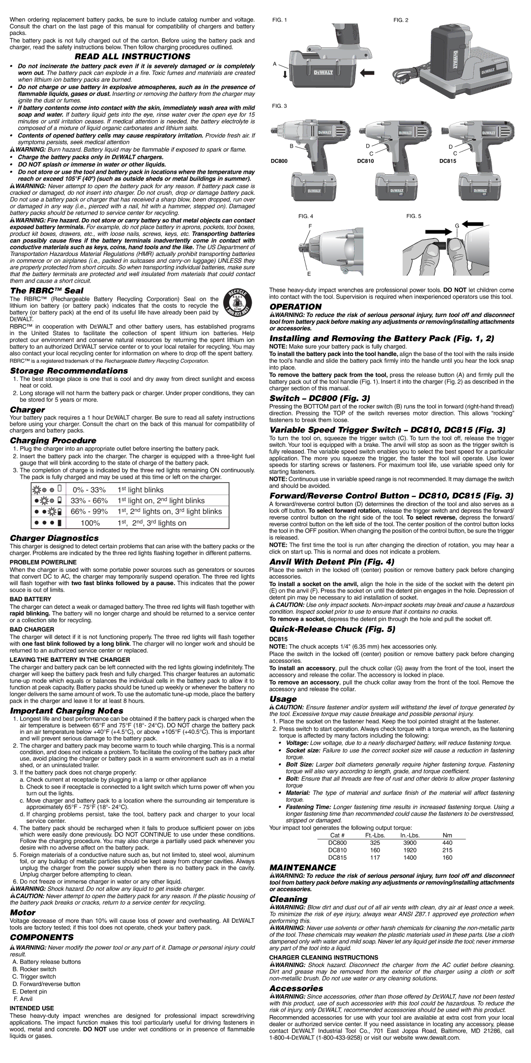
A. Battery release buttons
B. Rocker switch
C. Trigger switch
D. Forward/reverse button
E. Detent pin
F. Anvil
INTENDED USE
These heavy-duty impact wrenches are designed for professional impact screwdriving applications. The impact function makes this tool particularly useful for driving fasteners in wood, metal and concrete. DO NOT use under wet conditions or in presence of flammable liquids or gases.
A
FIG. 3
These heavy-duty impact wrenches are professional power tools. DO NOT let children come into contact with the tool. Supervision is required when inexperienced operators use this tool.
OPERATION
 WARNING: To reduce the risk of serious personal injury, turn tool off and disconnect tool from battery pack before making any adjustments or removing/installing attachments or accessories.
Installing and Removing the Battery Pack (Fig. 1, 2)
NOTE: Make sure your battery pack is fully charged.
To install the battery pack into the tool handle, align the base of the tool with the rails inside the tool’s handle and slide the battery pack firmly into the handle until you hear the lock snap into place.
To remove the battery pack from the tool, press the release button (A) and firmly pull the battery pack out of the tool handle (Fig. 1). Insert it into the charger (Fig. 2) as described in the charger section of this manual.
Switch – DC800 (Fig. 3)
Pressing the BOTTOM part of the rocker switch (B) runs the tool in forward (right-hand thread) direction. Pressing the TOP of the switch reverses motor direction. This allows “rocking” fasteners to break them loose.
Variable Speed Trigger Switch – DC810, DC815 (Fig. 3)
To turn the tool on, squeeze the trigger switch (C). To turn the tool off, release the trigger switch. Your tool is equipped with a brake. The anvil will stop as soon as the trigger switch is fully released. The variable speed switch enables you to select the best speed for a particular application. The more you squeeze the trigger, the faster the tool will operate. Use lower speeds for starting screws or fasteners. For maximum tool life, use variable speed only for starting fasteners.
NOTE: Continuous use in variable speed range is not recommended. It may damage the switch and should be avoided.
Forward/Reverse Control Button – DC810, DC815 (Fig. 3)
A forward/reverse control button (D) determines the direction of the tool and also serves as a lock off button. To select forward rotation, release the trigger switch and depress the forward/ reverse control button on the right side of the tool. To select reverse, depress the forward/ reverse control button on the left side of the tool. The center position of the control button locks the tool in the OFF position. When changing the position of the control button, be sure the trigger is released.
NOTE: The first time the tool is run after changing the direction of rotation, you may hear a click on start up. This is normal and does not indicate a problem.
Anvil With Detent Pin (Fig. 4)
Place the switch in the locked off (center) position or remove battery pack before changing accessories.
To install a socket on the anvil, align the hole in the side of the socket with the detent pin
(E)on the anvil (F). Press the socket on until the detent pin engages in the hole. Depression of detent pin may be necessary to aid installation of socket.
 CAUTION: Use only impact sockets. Non-impact sockets may break and cause a hazardous condition. Inspect socket prior to use to ensure that it contains no cracks.
To remove a socket, depress the detent pin through the hole and pull the socket off.
Quick-Release Chuck (Fig. 5)
DC815
NOTE: The chuck accepts 1/4" (6.35 mm) hex accessories only.
Place the switch in the locked off (center) position or remove battery pack before changing accessories.
To install an accessory, pull the chuck collar (G) away from the front of the tool, insert the accessory and release the collar. The accessory is locked in place.
To remove an accessory, pull the chuck collar away from the front of the tool. Remove the accessory and release the collar.
Usage
 CAUTION: Ensure fastener and/or system will withstand the level of torque generated by the tool. Excessive torque may cause breakage and possible personal injury.
1.Place the socket on the fastener head. Keep the tool pointed straight at the fastener.
2.Press switch to start operation. Always check torque with a torque wrench, as the fastening torque is affected by many factors including the following:
•Voltage: Low voltage, due to a nearly discharged battery, will reduce fastening torque.
•Socket size: Failure to use the correct socket size will cause a reduction in fastening torque.
•Bolt Size: Larger bolt diameters generally require higher fastening torque. Fastening torque will also vary according to length, grade, and torque coefficient.
•Bolt: Ensure that all threads are free of rust and other debris to allow proper fastening torque
•Material: The type of material and surface finish of the material will affect fastening torque.
•Fastening Time: Longer fastening time results in increased fastening torque. Using a longer fastening time than recommended could cause the fasteners to be overstressed, stripped or damaged.
Your impact tool generates the following output torque:
DC800 325 3900 440
DC810 160 1920 215
DC815 117 1400 160
MAINTENANCE
 WARNING: To reduce the risk of serious personal injury, turn tool off and disconnect tool from battery pack before making any adjustments or removing/installing attachments or accessories.
Cleaning
 WARNING: Blow dirt and dust out of all air vents with clean, dry air at least once a week. To minimize the risk of eye injury, always wear ANSI Z87.1 approved eye protection when performing this.
 WARNING: Never use solvents or other harsh chemicals for cleaning the non-metallic parts of the tool. These chemicals may weaken the plastic materials used in these parts. Use a cloth dampened only with water and mild soap. Never let any liquid get inside the tool; never immerse any part of the tool into a liquid.
CHARGER CLEANING INSTRUCTIONS
 WARNING: Shock hazard. Disconnect the charger from the AC outlet before cleaning. Dirt and grease may be removed from the exterior of the charger using a cloth or soft non-metallic brush. Do not use water or any cleaning solutions.
Accessories
 WARNING: Since accessories, other than those offered by DEWALT, have not been tested with this product, use of such accessories with this tool could be hazardous. To reduce the risk of injury, only DEWALT, recommended accessories should be used with this product.
Recommended accessories for use with your tool are available at extra cost from your local dealer or authorized service center. If you need assistance in locating any accessory, please contact DEWALT Industrial Tool Co., 701 East Joppa Road, Baltimore, MD 21286, call 1-800-4-DEWALT (1-800-433-9258) or visit our website www.dewalt.com.