NOTE: Align ribs on inside of depth locator with grooves in clutch housing before snapping into place.
CHANGING BIT TIP
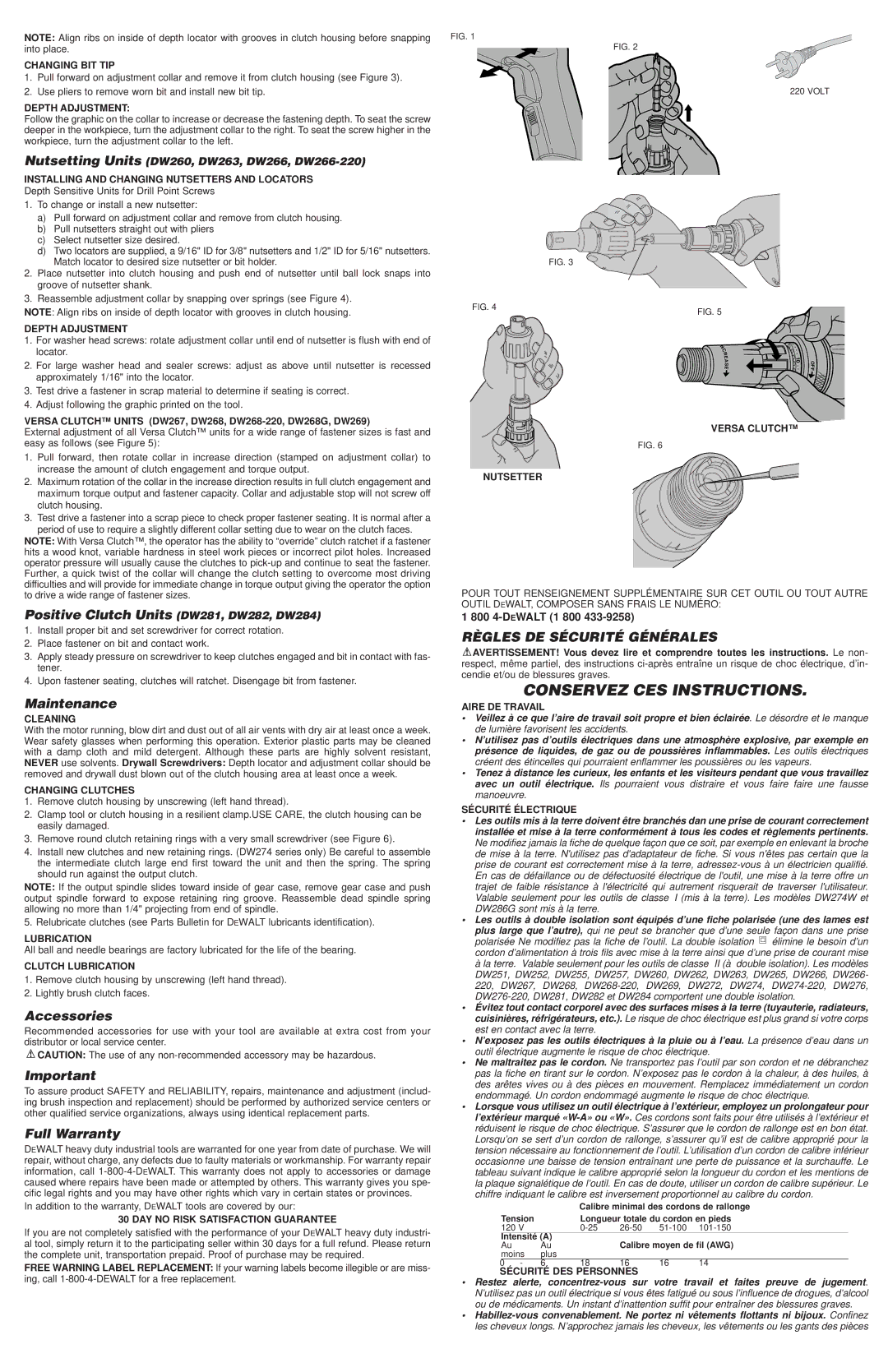
1.Pull forward on adjustment collar and remove it from clutch housing (see Figure 3).
2.Use pliers to remove worn bit and install new bit tip.
DEPTH ADJUSTMENT:
Follow the graphic on the collar to increase or decrease the fastening depth. To seat the screw deeper in the workpiece, turn the adjustment collar to the right. To seat the screw higher in the workpiece, turn the adjustment collar to the left.
Nutsetting Units (DW260, DW263, DW266, DW266-220)
INSTALLING AND CHANGING NUTSETTERS AND LOCATORS
Depth Sensitive Units for Drill Point Screws
1.To change or install a new nutsetter:
a)Pull forward on adjustment collar and remove from clutch housing.
b)Pull nutsetters straight out with pliers
c)Select nutsetter size desired.
d)Two locators are supplied, a 9/16" ID for 3/8" nutsetters and 1/2" ID for 5/16" nutsetters. Match locator to desired size nutsetter or bit holder.
2.Place nutsetter into clutch housing and push end of nutsetter until ball lock snaps into groove of nutsetter shank.
3.Reassemble adjustment collar by snapping over springs (see Figure 4).
NOTE: Align ribs on inside of depth locator with grooves in clutch housing.
DEPTH ADJUSTMENT
1.For washer head screws: rotate adjustment collar until end of nutsetter is flush with end of locator.
2.For large washer head and sealer screws: adjust as above until nutsetter is recessed approximately 1/16" into the locator.
3.Test drive a fastener in scrap material to determine if seating is correct.
4.Adjust following the graphic printed on the tool.
VERSA CLUTCH™ UNITS (DW267, DW268, DW268-220, DW268G, DW269)
External adjustment of all Versa Clutch™ units for a wide range of fastener sizes is fast and easy as follows (see Figure 5):
1.Pull forward, then rotate collar in increase direction (stamped on adjustment collar) to increase the amount of clutch engagement and torque output.
2.Maximum rotation of the collar in the increase direction results in full clutch engagement and maximum torque output and fastener capacity. Collar and adjustable stop will not screw off clutch housing.
3.Test drive a fastener into a scrap piece to check proper fastener seating. It is normal after a period of use to require a slightly different collar setting due to wear on the clutch faces.
NOTE: With Versa Clutch™, the operator has the ability to “override” clutch ratchet if a fastener hits a wood knot, variable hardness in steel work pieces or incorrect pilot holes. Increased operator pressure will usually cause the clutches to pick-up and continue to seat the fastener. Further, a quick twist of the collar will change the clutch setting to overcome most driving difficulties and will provide for immediate change in torque output giving the operator the option to drive a wide range of fastener sizes.
Positive Clutch Units (DW281, DW282, DW284)
1.Install proper bit and set screwdriver for correct rotation.
2.Place fastener on bit and contact work.
3.Apply steady pressure on screwdriver to keep clutches engaged and bit in contact with fas- tener.
4.Upon fastener seating, clutches will ratchet. Disengage bit from fastener.
Maintenance
CLEANING
With the motor running, blow dirt and dust out of all air vents with dry air at least once a week. Wear safety glasses when performing this operation. Exterior plastic parts may be cleaned with a damp cloth and mild detergent. Although these parts are highly solvent resistant, NEVER use solvents. Drywall Screwdrivers: Depth locator and adjustment collar should be removed and drywall dust blown out of the clutch housing area at least once a week.
CHANGING CLUTCHES
1.Remove clutch housing by unscrewing (left hand thread).
2.Clamp tool or clutch housing in a resilient clamp.USE CARE, the clutch housing can be easily damaged.
3.Remove round clutch retaining rings with a very small screwdriver (see Figure 6).
4.Install new clutches and new retaining rings. (DW274 series only) Be careful to assemble the intermediate clutch large end first toward the unit and then the spring. The spring should run against the output clutch.
NOTE: If the output spindle slides toward inside of gear case, remove gear case and push output spindle forward to expose retaining ring groove. Reassemble dead spindle spring allowing no more than 1/4" projecting from end of spindle.
5. Relubricate clutches (see Parts Bulletin for DEWALT lubricants identification).
LUBRICATION
All ball and needle bearings are factory lubricated for the life of the bearing.
CLUTCH LUBRICATION
1.Remove clutch housing by unscrewing (left hand thread).
2.Lightly brush clutch faces.
Accessories
Recommended accessories for use with your tool are available at extra cost from your distributor or local service center.
 CAUTION: The use of any non-recommended accessory may be hazardous.
Important
To assure product SAFETY and RELIABILITY, repairs, maintenance and adjustment (includ- ing brush inspection and replacement) should be performed by authorized service centers or other qualified service organizations, always using identical replacement parts.
Full Warranty
DEWALT heavy duty industrial tools are warranted for one year from date of purchase. We will repair, without charge, any defects due to faulty materials or workmanship. For warranty repair information, call 1-800-4-DEWALT. This warranty does not apply to accessories or damage caused where repairs have been made or attempted by others. This warranty gives you spe- cific legal rights and you may have other rights which vary in certain states or provinces.
In addition to the warranty, DEWALT tools are covered by our:
30 DAY NO RISK SATISFACTION GUARANTEE
If you are not completely satisfied with the performance of your DEWALT heavy duty industri- al tool, simply return it to the participating seller within 30 days for a full refund. Please return the complete unit, transportation prepaid. Proof of purchase may be required.
FREE WARNING LABEL REPLACEMENT: If your warning labels become illegible or are miss- ing, call 1-800-4-DEWALT for a free replacement.
FIG. 1
FIG. 2
220 VOLT
FIG. 3
FIG. 4
FIG. 5
N | . | |
. | |
C | . | |
R | | . | |
E | 10 | |
A | OF |
S | | . |
E | | . | F |
| | . | |
| 0 | |
| . | . | |
| | |
VERSA CLUTCH™
FIG. 6
NUTSETTER
POUR TOUT RENSEIGNEMENT SUPPLÉMENTAIRE SUR CET OUTIL OU TOUT AUTRE OUTIL DEWALT, COMPOSER SANS FRAIS LE NUMÉRO:
1 800 4-DEWALT (1 800 433-9258)
RÈGLES DE SÉCURITÉ GÉNÉRALES
 AVERTISSEMENT! Vous devez lire et comprendre toutes les instructions. Le non- respect, même partiel, des instructions ci-après entraîne un risque de choc électrique, d’in- cendie et/ou de blessures graves.
CONSERVEZ CES INSTRUCTIONS.
AIRE DE TRAVAIL
•Veillez à ce que l’aire de travail soit propre et bien éclairée . Le désordre et le manque de lumière favorisent les accidents.
•N’utilisez pas d’outils électriques dans une atmosphère explosive, par exemple en présence de liquides, de gaz ou de poussières inflammables. Les outils électriques créent des étincelles qui pourraient enflammer les poussières ou les vapeurs.
•Tenez à distance les curieux, les enfants et les visiteurs pendant que vous travaillez avec un outil électrique. Ils pourraient vous distraire et vous faire faire une fausse manoeuvre.
SÉCURITÉ ÉLECTRIQUE
•Les outils mis à la terre doivent être branchés dan une prise de courant correctement installée et mise à la terre conformément à tous les codes et règlements pertinents. Ne modifiez jamais la fiche de quelque façon que ce soit, par exemple en enlevant la broche de mise à la terre. N'utilisez pas d'adaptateur de fiche. Si vous n'êtes pas certain que la prise de courant est correctement mise à la terre, adressez-vous à un électricien qualifié. En cas de défaillance ou de défectuosité électrique de l'outil, une mise à la terre offre un trajet de faible résistance à l'électricité qui autrement risquerait de traverser l'utilisateur. Valable seulement pour les outils de classe I (mis à la terre). Les modèles DW274W et DW286G sont mis à la terre.
•Les outils à double isolation sont équipés d’une fiche polarisée (une des lames est
plus large que l’autre), qui ne peut se brancher que d’une seule façon dans une prise
polarisée Ne modifiez pas la fiche de l’outil. La double isolation  élimine le besoin d’un cordon d’alimentation à trois fils avec mise à la terre ainsi que d’une prise de courant mise
à la terre. Valable seulement pour les outils de classe II (à double isolation). Les modèles DW251, DW252, DW255, DW257, DW260, DW262, DW263, DW265, DW266, DW266- 220, DW267, DW268, DW268-220, DW269, DW272, DW274, DW274-220, DW276, DW276-220, DW281, DW282 et DW284 comportent une double isolation.
•Évitez tout contact corporel avec des surfaces mises à la terre (tuyauterie, radiateurs, cuisinières, réfrigérateurs, etc.). Le risque de choc électrique est plus grand si votre corps est en contact avec la terre.
•N’exposez pas les outils électriques à la pluie ou à l’eau. La présence d’eau dans un outil électrique augmente le risque de choc électrique.
•Ne maltraitez pas le cordon. Ne transportez pas l’outil par son cordon et ne débranchez pas la fiche en tirant sur le cordon. N’exposez pas le cordon à la chaleur, à des huiles, à des arêtes vives ou à des pièces en mouvement. Remplacez immédiatement un cordon endommagé. Un cordon endommagé augmente le risque de choc électrique.
•Lorsque vous utilisez un outil électrique à l’extérieur, employez un prolongateur pour l’extérieur marqué «W-A» ou «W». Ces cordons sont faits pour être utilisés à l’extérieur et réduisent le risque de choc électrique. S’assurer que le cordon de rallonge est en bon état. Lorsqu’on se sert d’un cordon de rallonge, s’assurer qu’il est de calibre approprié pour la tension nécessaire au fonctionnement de l’outil. L’utilisation d’un cordon de calibre inférieur occasionne une baisse de tension entraînant une perte de puissance et la surchauffe. Le tableau suivant indique le calibre approprié selon la longueur du cordon et les mentions de la plaque signalétique de l’outil. En cas de doute, utiliser un cordon de calibre supérieur. Le chiffre indiquant le calibre est inversement proportionnel au calibre du cordon.
Calibre minimal des cordons de rallonge
| Tension | | Longueur totale du cordon en pieds |
| 120 V | | 0-25 | 26-50 | 51-100 | 101-150 |
| Intensité (A) | | Calibre moyen de fil (AWG) |
| Au | Au | |
| moins | plus | | | | |
0 - | 6 | 18 | 16 | 16 | 14 |
SÉCURITÉ DES PERSONNES
•Restez alerte, concentrez-vous sur votre travail et faites preuve de jugement. N’utilisez pas un outil électrique si vous êtes fatigué ou sous l’influence de drogues, d’alcool ou de médicaments. Un instant d’inattention suffit pour entraîner des blessures graves.
•Habillez-vous convenablement. Ne portez ni vêtements flottants ni bijoux. Confinez les cheveux longs. N’approchez jamais les cheveux, les vêtements ou les gants des pièces