ASSEMBLY
Package contents:
• | 1 | • | 1 Allen wrench | ||
• | 1 | Water kit | • | 1 | Flange wrench |
• | Diamond blade | • | 1 | Instruction Manual | |
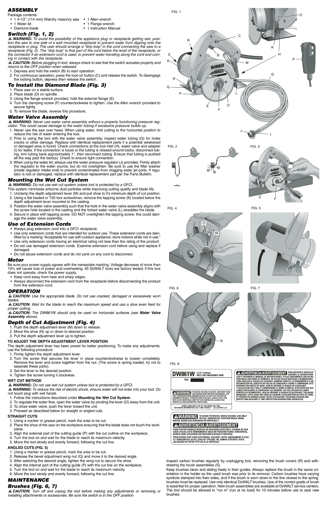
Switch (Fig. 1, 2)
![]() WARNING: To avoid the possibility of the appliance plug or receptacle getting wet, posi- tion the saw to one side of a wall mounted receptacle to prevent water from dipping onto the receptacle or plug. The user should arrange a “drip loop” in the cord connecting the saw to a receptacle (Fig. 2). The “drip loop” is that part of the cord below the level of the receptacle, or the connector if an extension cord is used, to prevent water traveling along the cord and com- ing in contact with the receptacle.
WARNING: To avoid the possibility of the appliance plug or receptacle getting wet, posi- tion the saw to one side of a wall mounted receptacle to prevent water from dipping onto the receptacle or plug. The user should arrange a “drip loop” in the cord connecting the saw to a receptacle (Fig. 2). The “drip loop” is that part of the cord below the level of the receptacle, or the connector if an extension cord is used, to prevent water traveling along the cord and com- ing in contact with the receptacle.
![]() CAUTION: Before plugging in tool, always check to see that the switch actuates properly and returns to the OFF position when released.
CAUTION: Before plugging in tool, always check to see that the switch actuates properly and returns to the OFF position when released.
1.Depress and hold the switch (B) to start operation.
2.For continuous operation, press the
To Install the Diamond Blade (Fig. 3)
1.Place saw on a stable surface.
2.Place blade (D) on spindle.
3.Using the flange wrench provided, hold the external flange (E)
4.Turn the clamping screw (F) counterclockwise to tighten. Use the Allen wrench provided to secure tightly.
5.To remove the blade, reverse this procedure.
Water Valve Assembly
![]() WARNING: Never use water valve assembly without a properly functioning pressure reg- ulator. This could cause damage to the water tubing if excessive pressure builds up.
WARNING: Never use water valve assembly without a properly functioning pressure reg- ulator. This could cause damage to the water tubing if excessive pressure builds up.
1. Never use the saw over head. When using water, limit cutting to the horizontal position to |
reduce the risk of water entering the tool. |
2. Prior to using the tool with the water valve assembly, inspect water tubing (G) for holes |
cracks or other damage. Replace with identical replacement parts if a potential weakened |
FIG. 1
R
S
R
N
Q
P ![]()
![]()
E
![]() O
O
C
K
B | H |
A
![]() M
M
G
L
D
F
J
I
or damaged area is found. Check connections at the tool inlet (H), water valve and adapter |
(I) for leaks. If the connection is loose or the tubing is relaxed around barbs, disconnect tub- |
ing, trim tubing back approximately 1", then reconnect tubing. Ensure that tubing is pushed |
all the way past the barb(s). Check to ensure tight connection. |
3. When using the water kit, always use the water pressure regulator (J) provided. Firmly attach |
the regulator to the water source, but do not overtighten. Be sure to use the filter washer |
(inside regulator intake end) to prevent contaminates from clogging water jet ports. If regu- |
lator is lost or damaged, replace with identical replacement part per the Parts Bulletin. |
Mounting the Wet Cut System
![]() WARNING: Do not use wet cut system unless tool is protected by a GFCI.
WARNING: Do not use wet cut system unless tool is protected by a GFCI.
This system minimizes airborne dust particles while improving cutting quality and blade life.
1.Unclamp the depth adjustment lever (M) and pull shoe to it’s minimum depth of cut position.
2.Using a flat bladed or T20 torx screwdriver, remove the tapping screw (K) located below the depth adjustment lever mounted to the casting.
3.Position the water valve assembly such that the hole in the water valve assembly aligns with the screw hole located in the casting and the forked water valve (L) straddles the blade.
4.Secure in place with tapping screw. DO NOT overtighten the tapping screw; this could dam- age the water valve assembly.
Use of Extension Cords
•Always plug extension cord into a GFCI receptacle.
•Use only extension cords that are intended for outdoor use. These extension cords are iden- tified by a marking “Acceptable for use with outdoor appliance; store indoors while not in use.”
•Use only extension cords having an electrical rating not less than the rating of the product.
•Do not use damaged extension cords. Examine extension cord before using and replace if damaged.
•Do not abuse extension cords and do not yank on any cord to disconnect.
Motor
Be sure your power supply agrees with the nameplate marking. Voltage decrease of more than 10% will cause loss of power and overheating. All DEWALT tools are factory tested; if this tool does not operate, check the power supply.
•Keep cord away from heat and sharp edges.
•Always disconnect the extension cord from the receptacle before disconnecting the product from the extension cord.
OPERATION
![]() CAUTION: Use the appropriate blade. Do not use cracked, damaged or excessively worn blades.
CAUTION: Use the appropriate blade. Do not use cracked, damaged or excessively worn blades.
![]() CAUTION: Wait for the blade to reach the maximum speed and use a slow even feed for proper cutting.
CAUTION: Wait for the blade to reach the maximum speed and use a slow even feed for proper cutting.
![]() CAUTION: The DW861W should only be used on horizontal surfaces (see Water Valve Assembly above).
CAUTION: The DW861W should only be used on horizontal surfaces (see Water Valve Assembly above).
Depth of Cut Adjustment (Fig. 4)
FIG. 2
FIG. 4
O
FIG. 6
FIG. 3
E
FIG. 5
M
FIG. 7
F
1.Push the depth adjustment lever (M) down to release.
2.Move the shoe (N) up or down to desired position.
3.Pull the depth adjustment lever up to tighten.
TO ADJUST THE DEPTH ADJUSTMENT LEVER POSITION
The depth adjustment lever has been preset for better positioning. To make any adjustments, use the following procedure:
1.Firmly tighten the depth adjustment lever.
2.Turn the screw that secures the lever in place counterclockwise to loosen completely. Remove the lever and screw together from the nut. (The screw is spring loaded, try not to separate these parts).
3.Set the lever to the desired position.
4.Tighten the screw turning it clockwise.
WET CUT METHOD
![]() WARNING: Do not use wet cut system unless tool is protected by a GFCI.
WARNING: Do not use wet cut system unless tool is protected by a GFCI.
![]() WARNING: To reduce the risk of electric shock, ensure water will not enter into your tool. Do not touch plug with wet hands.
WARNING: To reduce the risk of electric shock, ensure water will not enter into your tool. Do not touch plug with wet hands.
1.Follow the instructions described under Mounting the Wet Cut System.
2.To regulate the water flow, open the water valve by pivoting the lever (O) away from the unit.
3.To close water valve, push the lever toward the unit.
3. Proceed as described below for straight or angled cuts.
STRAIGHT CUTS
1.Using a marker or grease pencil, mark the area to be cut.
2.Place the shoe of the saw on the workpiece ensuring that the blade does not touch the work- piece.
3.Align the external part of the cutting guide (P) with the cut outline on the workpiece.
4.Turn the tool on and wait for the blade to reach its maximum velocity.
5.Move the tool slowly and evenly forward, following the cut line.
ANGLED CUTS (FIG. 5)
1.Using a marker or grease pencil, mark the area to be cut.
2.Release the bevel adjustment wing nut (Q) and move it to the desired angle.
3.After selecting the desired angle, tighten the wing nut to secure the shoe.
4.Align the internal part of the cutting guide (P) with the cut line on the workpiece.
5.Turn the tool on and wait for the blade to reach its maximum velocity.
6.Move the tool slowly and evenly forward, following the cut line.
MAINTENANCE
Brushes (Fig. 6, 7)
![]() CAUTION: Turn off and unplug the tool before making any adjustments or removing or installing attachments or accessories. Be sure the switch is in the OFF position.
CAUTION: Turn off and unplug the tool before making any adjustments or removing or installing attachments or accessories. Be sure the switch is in the OFF position.
![]() S
S
![]() R
R
FIG. 8
Inspect carbon brushes regularly by unplugging tool, removing the brush covers (R) and with- drawing the brush assemblies (S).
Keep brushes clean and sliding freely in their guides. Always replace the brush in the same ori- entation in the holder as the used brush was prior to its removal. Carbon brushes have varying symbols stamped into their sides, and if the brush is worn down to the line closest to the spring, brushes must be replaced. Use only identical DEWALT brushes. Use of the correct grade of brush is essential for proper operation. New brush assemblies are available at DEWALT service centers. The tool should be allowed to “run in” (run at no load) for 10 minutes before use to seat new brushes.