2.2) Connectors
a. Interface Connectors Refer to Interface explain.
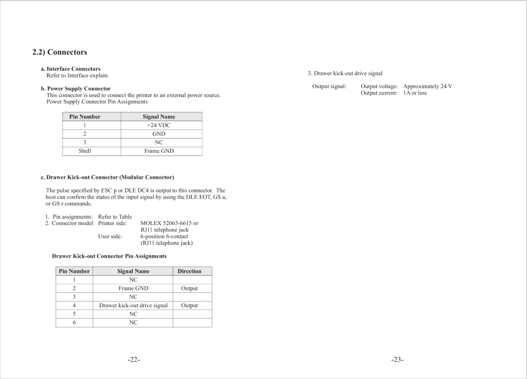
b. Power Supply Connector
This connector is used to connect the printer to an external power source. Power Supply Connector Pin Assignments
Pin Number | Signal Name |
1 | +24 VDC |
|
|
2 | GND |
|
|
3 | NC |
|
|
Shell | Frame GND |
|
|
c. Drawer Kick-out Connector (Modular Connector)
The pulse specified by ESC p or DLE DC4 is output to this connector. The host can confirm the status of the input signal by using the DLE EOT, GS a, or GS r commands.
1. | Pin assignments: Refer to Table |
|
2. | Connector model: Printer side: | MOLEX |
|
| RJ11 telephone jack |
| User side: | |
|
| (RJ11 telephone jack) |
Drawer
Pin Number | Signal Name | Direction |
1 | NC |
|
|
|
|
2 | Frame GND | Output |
|
|
|
3 | NC |
|
|
|
|
4 | Drawer | Output |
|
|
|
5 | NC |
|
|
|
|
6 | NC |
|
|
|
|
3. Drawer |
| |
Output signal: | Output voltage: | Approximately 24 V |
| Output current: | 1A or less |