ADDITIONAL TOOLS REQUIRED
∙RF Power Attenuator (30 dB, 150 watt, for transmitters with RF power beyond the capabilities of a Service Monitor)
∙Digital Voltmeter
∙Oscilloscope (optional)
|
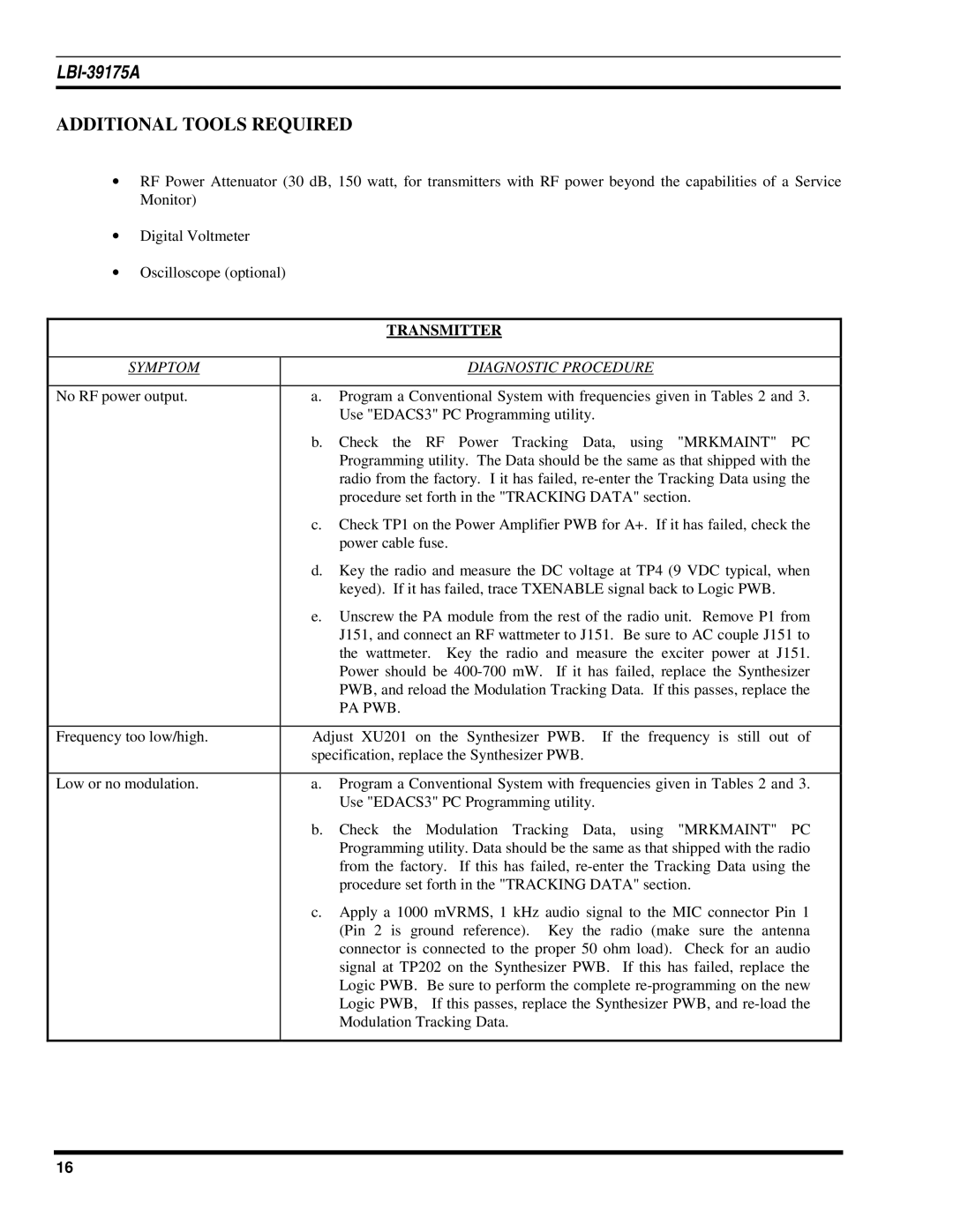
| TRANSMITTER | |
|
|
|
|
SYMPTOM |
|
| DIAGNOSTIC PROCEDURE |
|
|
| |
No RF power output. | a. | Program a Conventional System with frequencies given in Tables 2 and 3. | |
|
| Use "EDACS3" PC Programming utility. | |
| b. | Check the RF Power Tracking Data, using "MRKMAINT" PC | |
|
| Programming utility. The Data should be the same as that shipped with the | |
|
| radio from the factory. I it has failed, | |
|
| procedure set forth in the "TRACKING DATA" section. | |
| c. | Check TP1 on the Power Amplifier PWB for A+. If it has failed, check the | |
|
| power cable fuse. | |
| d. | Key the radio and measure the DC voltage at TP4 (9 VDC typical, when | |
|
| keyed). If it has failed, trace TXENABLE signal back to Logic PWB. | |
| e. | Unscrew the PA module from the rest of the radio unit. Remove P1 from | |
|
| J151, and connect an RF wattmeter to J151. Be sure to AC couple J151 to | |
|
| the wattmeter. Key the radio and measure the exciter power at J151. | |
|
| Power should be | |
|
| PWB, and reload the Modulation Tracking Data. If this passes, replace the | |
|
| PA PWB. |
|
|
|
| |
Frequency too low/high. | Adjust XU201 on | the Synthesizer PWB. If the frequency is still out of | |
| specification, replace the Synthesizer PWB. | ||
|
|
| |
Low or no modulation. | a. | Program a Conventional System with frequencies given in Tables 2 and 3. | |
|
| Use "EDACS3" PC Programming utility. | |
| b. | Check the Modulation Tracking Data, using "MRKMAINT" PC | |
|
| Programming utility. Data should be the same as that shipped with the radio | |
|
| from the factory. If this has failed, | |
|
| procedure set forth in the "TRACKING DATA" section. | |
| c. | Apply a 1000 mVRMS, 1 kHz audio signal to the MIC connector Pin 1 | |
|
| (Pin 2 is ground reference). Key the radio (make sure the antenna | |
|
| connector is connected to the proper 50 ohm load). Check for an audio | |
|
| signal at TP202 on the Synthesizer PWB. If this has failed, replace the | |
|
| Logic PWB. Be sure to perform the complete | |
|
| Logic PWB, | If this passes, replace the Synthesizer PWB, and |
|
| Modulation Tracking Data. | |
|
|
|
|
16