Fig. 3

Installation

CAUTION: Make sure that the mounting surface is strong enough to support the operating weight of the cooler when in use. (For operating weight, see Specification Table.)

CAUTION: Never start cooler until installation is complete and unit has been tested for rigidity.

CAUTION: This unit must be installed at a height of 10 feet or greater from the floor.

Electrical Installation

NOTE: Local building code regulations must be observed.

WARNING: Disconnect all electrical service that will be used for this unit before you begin the installation.

Connect electrical. Cooler must be connected to the proper line current, voltage and cycle, as indicated on the decal located at the electrical service entrance. Connecting improper voltage to motor will void motor warranty. See the wiring diagrams (figures 8 & 9) on page 3 for wiring electrical connections.

NOTE: A separate 120 Volt, 60 Hz, 1 phase pump electrical circuit is required to maintain the integrity of the GFCI pump protection and to maintain the U.L. Listing of the evaporative cooler.

Wire gage. The horse power, voltage, cycle, phase, current, and length of wire required from switch to motor will determine the gauge of wire to be used.

Switches. Larger horsepower and three phase applications require switches (not supplied) of proper current capacity and should be installed by a competent electrician.

Connect water supply line. A water supply line should be run to the cooler to supply an adequate amount of cold water to the unit. The amount of water each cooler uses will depend on the weather conditions in your area and the size of your unit. The hotter and dryer your climate and the higher the capacity of your unit, the more water will evaporate. For example: An FAD248 unit with a 2 hp motor will use approximately 85 gallons per hour in a hot and dry climate like Las Vegas on a 105°F day with 10% humidity. The same unit in a cooler climate with 95°F and 20% humidity would use approximately 63 gph.

NOTE: Do not connect the water supply line to any soft water applications.

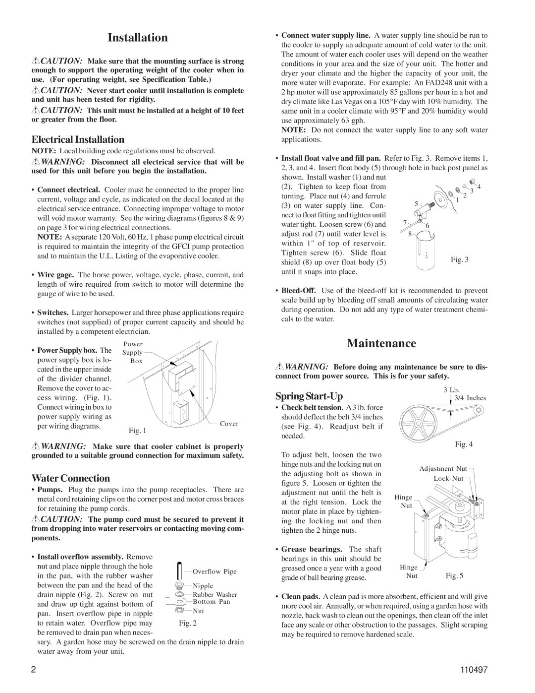
Install float valve and fill pan. Refer to Fig. 3. Remove items 1,

2, 3, and 4. Insert float body (5) through hole in back post panel as

shown. Install washer (1) and nut


(2). Tighten to keep float from


2

3 4

turning. Place nut (4) and ferrule


5

1


(3) on water supply line. Con-


nect to float fitting and tighten until

7


water tight. Loosen screw (6) and


6


adjust rod (7) until water level is


8


within 1" of top of reservoir. Tighten screw (6). Slide float shield (8) up over float body (5) until it snaps into place.

Bleed-Off.Use of the bleed-off kit is recommended to prevent scale build up by bleeding off small amounts of circulating water during operation. Do not add any type of water treatment chemi- cals to the water.

Power Supply box. The

power supply box is lo-

cated in the upper inside

of the divider channel.

Power

Supply

Box

Maintenance

WARNING: Before doing any maintenance be sure to dis- connect from power source. This is for your safety.

Remove the cover to ac-

cess wiring. (Fig. 1).

Connect wiring in box to

power supply wiring as

per wiring diagrams.

Cover

Fig. 1

Spring Start-Up

Check belt tension. A 3 lb. force

should deflect the belt 3/4 inches

(see Fig. 4). Readjust belt if

needed.

3 Lb.

3/4 Inches

WARNING: Make sure that cooler cabinet is properly grounded to a suitable ground connection for maximum safety.

Water Connection

Pumps. Plug the pumps into the pump receptacles. There are metal cord retaining clips on the corner post and motor cross braces for retaining the pump cords.

CAUTION: The pump cord must be secured to prevent it from dropping into water reservoirs or contacting moving com- ponents.

Install overflow assembly. Remove


nut and place nipple through the hole

Overflow Pipe

in the pan, with the rubber washer


between the pan and the head of the

Nipple

To adjust belt, loosen the two

hinge nuts and the locking nut on

the adjusting bolt as shown in

figure 5. Loosen or tighten the

adjustment nut until the belt is

at the right tension. Lock the

motor plate in place by tighten-

ing the locking nut and then

tighten the 2 hinge nuts.

Grease bearings. The shaft

bearings in this unit should be

greased once a year with a good

grade of ball bearing grease.

Fig. 4

Adjustment Nut

Lock-Nut

Hinge

Nut

Hinge

Fig. 5

Nut

drain nipple (Fig. 2). Screw on nut

Rubber Washer

and draw up tight against bottom of

Bottom Pan

pan. Insert overflow pipe in nipple

Nut

to retain water. Overflow pipe may

Fig. 2

be removed to drain pan when neces-


sary. A garden hose may be screwed on the drain nipple to drain water away from your unit.

Clean pads. A clean pad is more absorbent, efficient and will give more cool air. Annually, or when required, using a garden hose with nozzle, back wash to clean out the openings, then clean off the inlet face any scale or other obstruction to the passages. Slight scraping may be required to remove hardened scale.

2

110497

Page 2
Image 2
Essick Air FAD248, FAD242 Installation, Maintenance, Install float valve and fill pan. Refer to . Remove items

FAD242, FAD248 specifications

Essick Air's FAD248 and FAD242 evaporative coolers are engineered to enhance indoor comfort and air quality, making them popular choices for residential and commercial spaces. Both models utilize a natural and energy-efficient cooling process, providing a refreshing respite from heat during the warmer months.

The FAD248 model is noted for its significant cooling capacity, making it suitable for medium to large-sized rooms. It features a powerful motor that delivers a high air output, ensuring that even the hottest spaces can maintain a comfortable temperature. On the other hand, the FAD242 is designed for slightly smaller areas, providing ample cooling with a slightly lower output while maintaining energy efficiency.

Both models employ advanced evaporative cooling technology that operates by drawing warm air through water-saturated pads. As the air passes through these pads, moisture evaporates, consequently lowering the air temperature. This process not only cools the air but also adds beneficial humidity, which can alleviate dryness and improve respiratory comfort.

The construction of the FAD248 and FAD242 includes durable, high-quality materials designed to withstand the rigors of continuous use. The exterior housing is typically constructed from robust plastics that are resistant to wear and tear, ensuring longevity. Furthermore, both coolers are equipped with large water reservoirs, allowing for extended periods of operation without the need for constant refilling.

In terms of usability, the FAD248 and FAD242 incorporate user-friendly controls that allow for easy adjustments to fan speed, cooling settings, and oscillation options, providing users with the flexibility to customize their cooling experience. Many models include a remote control feature for added convenience, allowing users to operate the unit from a distance.

Energy efficiency is a key highlight of both the FAD248 and FAD242, designed with efficiency in mind to minimize electricity consumption. This means users can enjoy cooler indoor environments without incurring high energy costs, making these coolers an environmentally friendly choice.

In summary, the Essick Air FAD248 and FAD242 evaporative coolers are practical solutions for effective and energy-efficient cooling. With user-centered designs, durable construction, and advanced evaporative technologies, they contribute significantly to enhanced indoor air quality and comfort, catering to the needs of different room sizes while promoting an eco-friendly lifestyle.