Manuals
/
Eurotech Appliances
/
Computer Equipment
/
Computer Hardware
Eurotech Appliances
CPU-1461
user manual
Models:
CPU-1461
1
13
69
69
Download
69 pages
24.22 Kb
10
11
12
13
14
15
16
17
Troubleshooting
Operating Characteristics
Error Handling Page
Watch Dog Timer
Warranty
Dimension
ƒ System reset
Connectors Layout
BIOS Flash
Default
Page 13
Image 13
Page 12
Page 14
Page 13
Image 13
Page 12
Page 14
Contents
EmbeddedDNA
CPU-1461
User’s Manual
COPYRIGHT 1994-2005 Eurotech S.p.A. All Rights Reserved
PC/104-Plus - CPU-1461 Module
Conventions
Environmental safety
Important features or
Icon
Page
Multifunction Connector Section
Contents
Contents
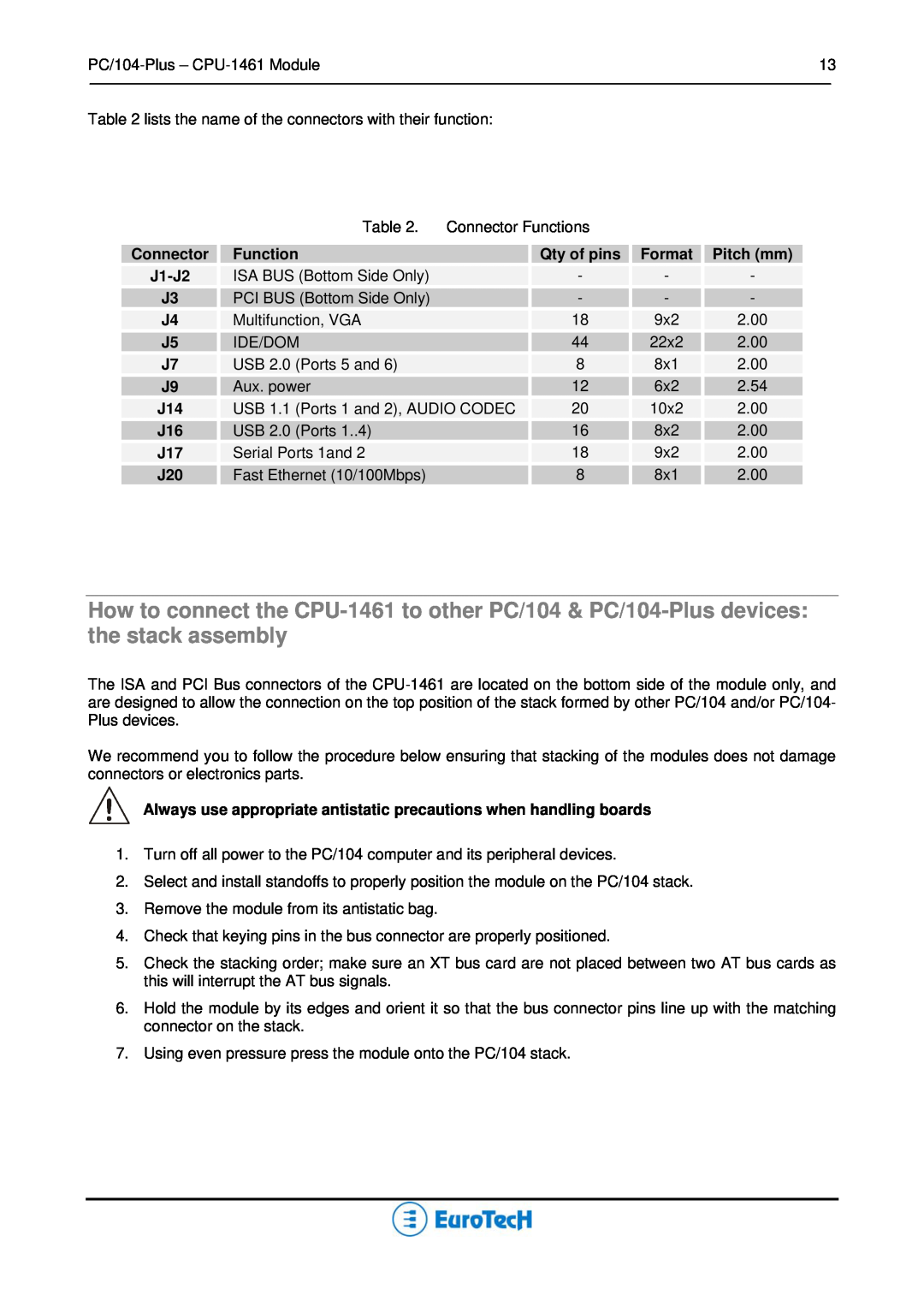
Connectors Description
Chapter 6 Troubleshooting
Chapter 5 Watch Dog Timer
Chapter 4 The Set-up Program
Appendix
Chapter 1 Product Overview
BIOS Flash
Product Definition
Power Supply
Architecture
Chapter 2 Jumper Description
Default
Jumper Layout and Configuration
Jumper #
Type
Chapter 3 Connectors Description
Note in figure 2, a red square pad indicates pin 1 of each connector
Connectors Layout
J14 J16 J17
J4J5
Page
CPU-1461
J4 for Multifunction and VGA
Carrier Module
Multifunction Connector Section
ƒ System reset
The Eurotech Multifunction Adapter
ƒ External Battery
ƒ Speaker
Supported CRT-VGA Video Resolutions
VGA Section
IDE/DOM
J5 IDE Connector
USB
J7 for USB 2.0 Ports 5 and
Power
J9 Auxiliary Power Connector
Power button input
Auxiliary
The Eurotech USB & AC97-Audio Codec Adapter
J14 for USB 1.1 Ports 7 and 8 and Audio-CODEC
Aux IN CD IN
To J14 CPU Board Connector
Aux IN
SpkPhone IN/OUT
J16 for USB 2.0 Ports 1to
J17 for SERIAL1 and SERIAL2
Ethernet
J20 for Ethernet
To CPU Board NetConnector
The Eurotech Ethernet Transceiver
RJ45 Connector
Chapter 4 The Set-up Program
Use the cursor arrow keys to move the highlight to other options
Select “Quit” to exit from the Setup program
Press the “ESC” key to return to the items of the Main menu
The follow screen will be displayed
General Page
The Set-up pages
Time
Quick Boot
Date
Floppy disks
Boot Try Sequence
Devices Page
Floppy Controller
Video Controller
Primary and secondary EIDE
AC97 Controller
Network
Serial Ports 1 and
Communications Page
VP2000 and VT100
Parallel Port
Parallel Port Mode
ATAPI unit type
Primary and Secondary ATAPI Page
Translation Mode
PIO Mode
Cylinders
Heads
Detect Now
Advanced page
ISA IRQ
PCI Advanced Page
Latency Time Devices
ISA Bus
Error Handling Page
Error on Video
Error on Keyboard
Error on Floppy Disks
Error on Fixed Disks
Page
This chapter explains how to use the Watch Dog timer
Chapter 5 Watch Dog Timer
How to use the Watch Dog
What is a Watch Dog?
Use the System BIOS INT 52h functions
How to turn the Watch Dog ON
How to turn the Watch Dog OFF
Directly accessing Watch Dog I/O mapped registers
Use the following code to Enable Watch Dog
Use following code to refresh the Watch Dog
Chapter 6 Troubleshooting
Troubleshooting a PC/104 System
Common Problems and Solutions
Technical/Sales Assistance
CPU Module doesn’t work
ftp//ftp.eurotech.it
Returning For Service
Page
Company Name
Page
Appendix
Operating Characteristics
A.1 Electrical and Environmental Specifications
Electrical Operating Characteristics
Backup Battery Characteristics
MTBF Mean Time Between Failures
Absolute Maximum Ratings
The CPU-1461 mechanical dimensions are shown in the following picture
A.2 Mechanical Dimensions
¾ Dimensions 90 X 96 mm 3.6”X3.8”
CPU-1461 Board dimensions
Ethernet Adapter Dimensions
USB Audio Codec Dimensions
Multifunction Adapter Dimensions
A.3 Safety Summary
62.0
12.0
Observe Dangerous Procedure Warnings
Use Caution When Exposing or Handling the CRT
Ground the Instrument
Do Not Operate in an Explosive Atmosphere
Reliability
Disclaimer of Warranty
Life Support Policy
B BIOS
Glossary
A ATA
ATAPI
C CELLULAR
G GPS
MPEG
M MIDI
N NDIS
NTSC
S SCSI
R RAM
SECAM
SMBus
W WAN
V VGA
Acronyms and Abbreviations
Page
techsupp@eurotech.it
Technical & Sales Assistance
ftp//ftp.eurotech.it
Top
Page
Image
Contents