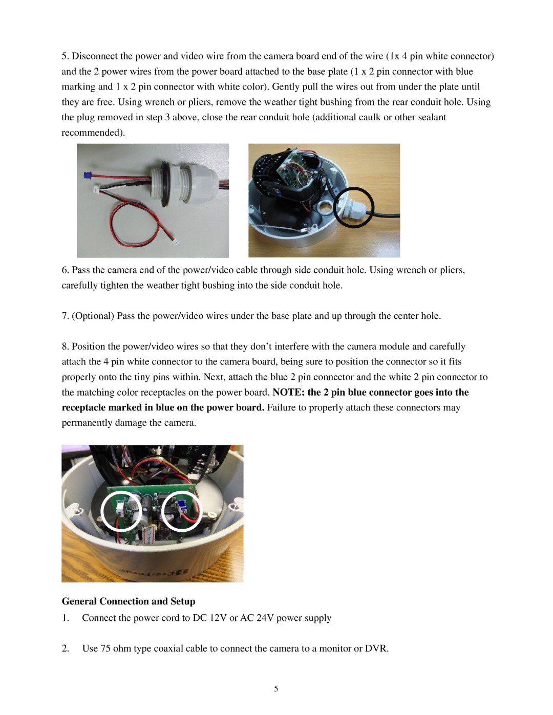
5.Disconnect the power and video wire from the camera board end of the wire (1x 4 pin white connector) and the 2 power wires from the power board attached to the base plate (1 x 2 pin connector with blue marking and 1 x 2 pin connector with white color). Gently pull the wires out from under the plate until they are free. Using wrench or pliers, remove the weather tight bushing from the rear conduit hole. Using the plug removed in step 3 above, close the rear conduit hole (additional caulk or other sealant recommended).
6.Pass the camera end of the power/video cable through side conduit hole. Using wrench or pliers, carefully tighten the weather tight bushing into the side conduit hole.
7.(Optional) Pass the power/video wires under the base plate and up through the center hole.
8.Position the power/video wires so that they don’t interfere with the camera module and carefully attach the 4 pin white connector to the camera board, being sure to position the connector so it fits properly onto the tiny pins within. Next, attach the blue 2 pin connector and the white 2 pin connector to the matching color receptacles on the power board. NOTE: the 2 pin blue connector goes into the receptacle marked in blue on the power board. Failure to properly attach these connectors may permanently damage the camera.
General Connection and Setup
1.Connect the power cord to DC 12V or AC 24V power supply
2.Use 75 ohm type coaxial cable to connect the camera to a monitor or DVR.
5
