Maintenance

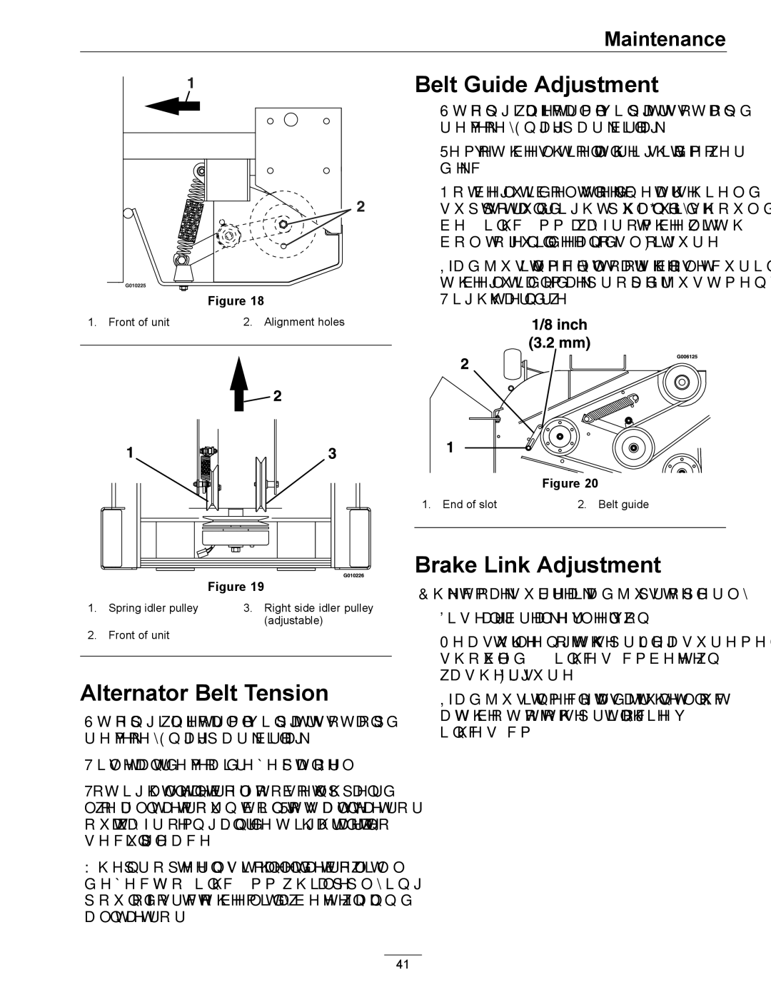
Figure 18

1. Front of unit


2. Alignment holes


Figure 19

1.

Spring idler pulley

3. Right side idler pulley

2.

Front of unit

(adjustable)


Alternator Belt Tension

Stop engine, wait for all moving parts to stop and remove key. Engage parking brake.

Tilt seat and remove air deflector panel

To tighten alternator belt, loosen both upper and lower alternator mounting bolts. Rotate alternator out, away from engine and retighten hardware to secure in place.

When properly tensioned, the alternator belt will deflect 1/4 to 3/8 inch (7-9 mm) while applying 22 pounds of force to the belt midway between fan and alternator.

Belt Guide Adjustment

1.Stop engine, wait for all moving parts to stop, and remove key. Engage parking brake.

2.Remove the belt shield on the right side of mower deck.

3.Note belt guide bolted to deck near the shield support stud and right-hand pulley. Guide should be 1/8 inch (3.2 mm) away from the belt, with bolt-end of guide near end of slot (Figure 20).

4.If adjustment is necessary, loosen the bolt securing the belt guide and make proper adjustment. Tighten hardware.

Figure 20

1. End of slot

2. Belt guide


Brake Link Adjustment

Check to make sure brake is adjusted properly.

1.Disengage brake lever (lever down).

2.Measure the length of the spring. Measurement should be 2 13/16 inches (7.1 cm) between washers. (Figure 21).

3.If adjustment is necessary, adjust the nyloc nut at the bottom of the spring to achieve 2 13/16 inches (7.1 cm).

41

Page 41
Image 41
Exmark 920 manual Alternator Belt Tension, Belt Guide Adjustment, Brake Link Adjustment

0, 920 specifications

The Exmark 920 is an exceptional piece of equipment tailored for professionals and enthusiasts alike. Designed with an emphasis on performance and reliability, this mower embodies the pinnacle of lawn care technology. Known for its robust construction, the Exmark 920 is equipped with a powerful engine, ensuring efficient and effective mowing even in demanding conditions.

One of the standout features of the Exmark 920 is its cutting deck. With a 52-inch or 60-inch mower deck option, it allows users to cover a large mowing area quickly. The deck is crafted from high-strength steel, providing durability and longevity while maintaining a lightweight design that enhances maneuverability. Innovative blade design promotes superior airflow for an even cut, preventing clumping and ensuring a polished finish across various grass types.

The Exmark 920 utilizes advanced technology, including the innovative RED Technology, which enhances engine performance by optimizing power consumption. This results in reduced fuel consumption while maintaining the required power output for demanding tasks. Additionally, the mower’s intuitive controls include a user-friendly interface, allowing for easy adjustments and settings, catering to the varying needs of different lawn types and conditions.

Another notable feature of the Exmark 920 is its all-day comfort design. With an ergonomic seat and advanced suspension system, operators can tackle long mowing sessions without discomfort. The padded seat is adjustable, providing maximum support to minimize fatigue, while the suspension system absorbs bumps and uneven terrain for a smoother ride.

Furthermore, the Exmark 920 prioritizes serviceability. Easy access points for maintenance and a well-designed layout ensure that routine tasks, such as oil changes and blade replacements, can be completed efficiently. The model also comes equipped with LED headlights for improved visibility during early morning or late evening mowing.

In summary, the Exmark 920 is a sophisticated mower combining power, advanced technology, and design for comfort and utility. Its high-performance engine, durable cutting deck, user-friendly controls, and serviceable layout make it an ideal choice for anyone seeking to achieve a well-manicured lawn with professional results. Whether for commercial or residential use, the Exmark 920 stands out as a leading option in the market, enabling users to tackle any mowing challenge with confidence and ease.