LEFT HAND
SIDE SHOWN
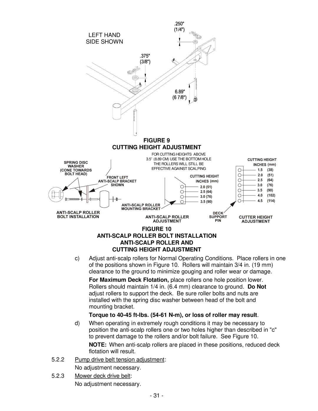
FIGURE 9
CUTTING HEIGHT ADJUSTMENT
FOR CUTTING HEIGHTS ABOVE
3.5” (8.89 CM) USE ![]() THE BOTTOM HOLE
THE BOTTOM HOLE
THE ROLLERS WILL STILL BE ![]() EFFECTIVE AGAINST SCALPING
EFFECTIVE AGAINST SCALPING
FIGURE 10
CUTTING HEIGHT ADJUSTMENT
c)Adjust
For Maximum Deck Flotation, place rollers one hole position lower. Rollers should maintain 1/4 in. (6.4 mm) clearance to ground. Do Not adjust rollers to support the deck. Be sure roller bolts and nuts are installed with the spring disc washer between head of the bolt and mounting bracket.
Torque to
d)When operating in extremely rough conditions it may be necessary to position the
NOTE: When
5.2.2Pump drive belt tension adjustment: No adjustment necessary.
5.2.3Mower deck drive belt: No adjustment necessary.
-31 -