Installation & Operation
Inertia installation and Operation
The INERTIA Graphics
•Because the INERTIA has two buffered outputs, it can simultaneously drive LCD products and any VGA compatible video display, such as:
•A front panel switch enables selection of either VGA 31.5 kHz (640 x 480) or Super VGA 35 kHz (800 x 600). With VGA or SVGA selected, both of the INERTIA’s outputs (RGBS on BNCs and VGA on
•A third output (labeled Monitor Output) is provided so that the computer’s local monitor can display the original
Installation
1.Turn the computer and monitor power OFF.
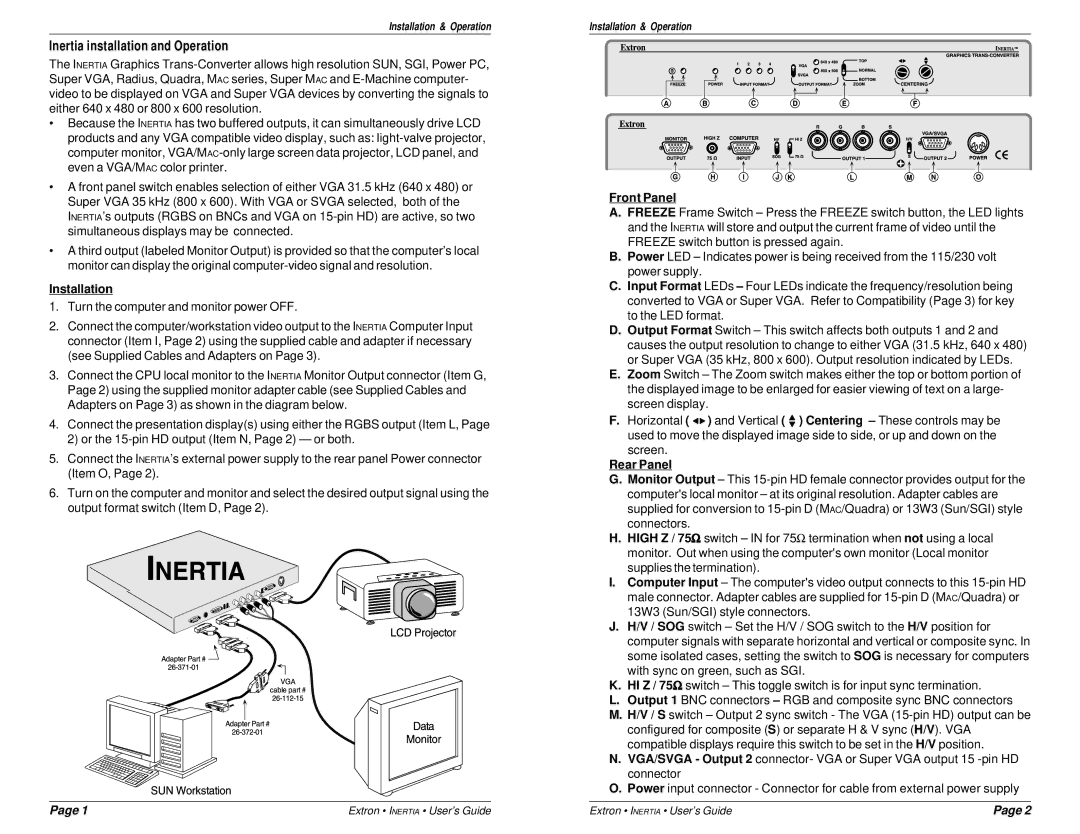
2.Connect the computer/workstation video output to the INERTIA Computer Input connector (Item I, Page 2) using the supplied cable and adapter if necessary (see Supplied Cables and Adapters on Page 3).
3.Connect the CPU local monitor to the INERTIA Monitor Output connector (Item G, Page 2) using the supplied monitor adapter cable (see Supplied Cables and Adapters on Page 3) as shown in the diagram below.
4.Connect the presentation display(s) using either the RGBS output (Item L, Page 2) or the
5.Connect the INERTIA’s external power supply to the rear panel Power connector (Item O, Page 2).
6.Turn on the computer and monitor and select the desired output signal using the output format switch (Item D, Page 2).
Installation & Operation
Front Panel
A.FREEZE Frame Switch – Press the FREEZE switch button, the LED lights and the INERTIA will store and output the current frame of video until the FREEZE switch button is pressed again.
B.Power LED – Indicates power is being received from the 115/230 volt power supply.
C.Input Format LEDs – Four LEDs indicate the frequency/resolution being converted to VGA or Super VGA. Refer to Compatibility (Page 3) for key to the LED format.
D.Output Format Switch – This switch affects both outputs 1 and 2 and causes the output resolution to change to either VGA (31.5 kHz, 640 x 480) or Super VGA (35 kHz, 800 x 600). Output resolution indicated by LEDs.
E.Zoom Switch – The Zoom switch makes either the top or bottom portion of the displayed image to be enlarged for easier viewing of text on a large- screen display.
F.Horizontal ( ![]()
![]() ) and Vertical (
) and Vertical ( ![]() ) Centering – These controls may be
) Centering – These controls may be
used to move the displayed image side to side, or up and down on the screen.
Rear Panel
G.Monitor Output – This
H.HIGH Z / 75Ω switch – IN for 75Ω termination when not using a local monitor. Out when using the computer's own monitor (Local monitor supplies the termination).
I.Computer Input – The computer's video output connects to this
J.H/V / SOG switch – Set the H/V / SOG switch to the H/V position for computer signals with separate horizontal and vertical or composite sync. In some isolated cases, setting the switch to SOG is necessary for computers with sync on green, such as SGI.
K.HI Z / 75Ω switch – This toggle switch is for input sync termination.
L.Output 1 BNC connectors – RGB and composite sync BNC connectors
M.H/V / S switch – Output 2 sync switch - The VGA
N.VGA/SVGA - Output 2 connector- VGA or Super VGA output 15
O.Power input connector - Connector for cable from external power supply
Page 1 | Extron • INERTIA • User’s Guide | Extron • INERTIA • User’s Guide | Page 2 |