BBG 6 A J, BBG 6 A specifications
The Extron Electronics BBG 6 A is a powerful and versatile product designed to accommodate a variety of audio and video system integration needs. This innovative device is particularly well-suited for installations in educational settings, corporate environments, and other professional applications. With a focus on user convenience and high-quality performance, the BBG 6 A stands out as an essential tool for any AV system designer or integrator.One of the main features of the Extron BBG 6 A is its ability to handle multiple audio sources simultaneously. The device supports up to six balanced mono or stereo audio signals, providing flexibility for diverse input sources. This capability ensures that users can seamlessly integrate various audio equipment, such as microphones, mixers, and playback devices, without compromising sound quality.
The BBG 6 A also incorporates advanced signal processing technologies. Its built-in signal routing flexibility allows users to switch between different input sources easily. Additionally, the device offers automatic gain control, which ensures that audio levels are consistently maintained, preventing sudden volume changes that could disrupt presentations or performances. This feature is particularly beneficial in environments where multiple users may access the same audio system.
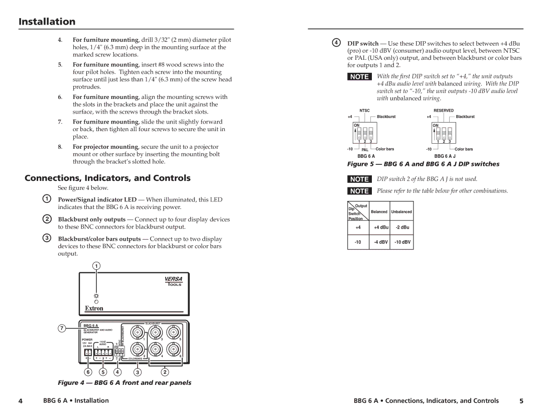
In terms of connectivity, the Extron BBG 6 A is equipped with various input and output options. The device includes standard 3-pin terminal blocks for audio inputs, ensuring reliable and secure connections. With balanced audio outputs, users can connect the BBG 6 A to amplifiers or other audio processing equipment with minimal interference, resulting in a clearer sound experience.
Another noteworthy characteristic of the BBG 6 A is its compact and lightweight design. This makes it easy to install in tight spaces or mobile setups, increasing its versatility for different applications. Moreover, the unit is designed with durability in mind, featuring a robust build that ensures longevity even in demanding environments.
Lastly, the intuitive user interface of the BBG 6 A simplifies operation for end-users. With straightforward controls and clear indicators, users can easily navigate the system without the need for extensive training. This focus on user experience enhances the overall efficiency and effectiveness of AV presentations and installations.
In summary, the Extron Electronics BBG 6 A is a sophisticated audio processing solution that combines multiple input handling, advanced signal processing, and user-friendly design. Its features make it an ideal choice for professionals seeking to elevate their audio integration capabilities in various settings.

