DMP 128 • Setup Guide
|
|
|
|
|
|
|
|
|
| : |
| for | the | |
|
|
|
|
|
|
| TANT |
|
|
| ||||
|
|
| IMPOR |
|
| .com |
|
|
| |||||
|
|
| on | installation | ||||||||||
|
|
|
|
|
| .extr | and | |||||||
| to | www |
|
|
|
|
|
| the | |||||
Refer |
| user |
|
| econnectingce | |||||||||
|
|
|
|
|
| guide |
| sour | . | |||||
complete |
|
| befor |
|
|
| ||||||||
|
| power |
|
|
| |||||||||
|
|
|
| the |
|
|
| |||||||
instructions |
|
|
|
|
|
|
|
| ||||||
product | to |
|
|
|
|
|
|
|
| |||||
|
|
|
|
|
|
|
|
|
|
| ||||
This guide provides basic instructions for an experienced technician to install the DMP 128 ProDSP™ Digital Matrix Processor. For additional information and specifications, see the DMP 128 product page at www.extron.com.
Disconnect Power and Mount the DMP 128
Disconnect power to the DMP 128 and turn off all devices that will be connected to it. The DMP 128 is housed in a full rack width,
8.5inch deep, 1U high metal enclosure that can sit on a table with the provided rubber feet or can be rack mounted. Select a suitable mounting location, then choose an appropriate mounting option.
Make all external device connections before applying power.
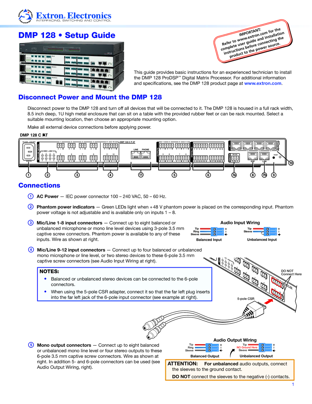
DMP 128 C PAT
MIC/LINE INPUTS
50/60 Hz
50/60HZZ
| MIC/LINEI INPUTISTS | 1 | 2 | 3 | 4 | 9 | 10 | DMP 128 C P AT |
|
|
| 1 | 2 | 3 | 4 |
|
|
|
|
| DIGITAL I/O |
|
|
|
|
|
|
|
|
|
|
|
| |||
|
|
|
| 4 | 9 |
| DMP 1288CCPP AT |
|
|
|
|
|
|
|
|
|
|
|
|
|
|
|
|
|
|
|
|
|
|
| ||||||
|
|
|
|
|
|
|
|
|
|
|
|
|
| I/O |
|
|
|
|
|
|
|
|
| AT |
|
|
|
|
|
|
| |||||
|
|
|
|
|
|
|
|
|
| LINE | PHONE | O | OUTPUTS |
|
|
|
| 1 | 2 | 3 | 4 5 | G |
| 6 7 | 8 | 9 10 G |
|
|
|
|
|
|
| |||
5 5 | 6 6 | 77 | 8 |
|
|
|
|
|
| U |
|
|
|
| DIGITAL | 11 12 13 14 15 G |
| 16 17 18 19 20 G | REMOTE | Tx Rx G |
|
| EXP |
| LAN | |||||||||||
MIC +48V |
|
|
|
|
|
|
|
|
|
|
|
| 1 | 2 | 3 | 4 5 |
| 6 | 7 | 8 | 9 100 |
| 1 |
| 2 | 1 | 3 | 2 | 4 | 3 | 4 | |||||
|
|
|
|
|
|
| LINE |
| T |
|
|
|
|
|
|
|
| |||||||||||||||||||
1 | 2 | 3 | 4 |
|
|
|
|
|
|
|
|
|
|
|
|
|
|
|
|
|
|
|
|
|
|
|
| EXP |
| LAN |
|
|
|
| ||
5 | 6 | 7 | 8 | 11 | 12 |
| P |
| 5 | 6 | 7 | 8 |
|
|
|
|
|
|
|
|
|
|
|
|
|
|
|
|
| |||||||
|
| MIC |
|
|
|
|
|
|
|
|
|
|
|
|
|
|
|
|
|
|
|
| RESET | |||||||||||||
|
| +48V |
|
|
|
|
|
|
|
|
| U |
|
|
|
|
| 11 12 |
|
|
|
|
| 118 |
|
|
|
|
|
|
|
| ||||
|
|
|
|
|
| 8 | 11 |
|
|
|
|
|
|
|
|
|
|
|
|
|
|
|
|
|
|
|
|
|
|
|
| |||||
1 | 2 | 3 | 4 |
|
|
|
|
|
| T |
|
|
|
|
|
|
|
|
|
|
|
|
|
|
|
|
|
|
|
|
|
|
|
| ||
|
|
|
|
|
|
|
|
|
|
|
|
|
|
|
|
|
|
|
|
|
|
|
|
|
|
|
|
|
|
|
| |||||
|
|
|
|
|
|
|
|
|
|
|
| S |
|
|
|
|
|
|
|
|
|
|
|
|
|
|
|
|
|
|
|
|
|
|
|
|
|
|
|
|
|
|
|
|
|
|
|
|
|
|
|
|
|
|
|
|
|
|
|
|
|
|
|
| TxRx |
|
|
|
|
|
|
|
|
Connections
A B
AC Power — IEC power connector 100 – 240 VAC, 50 – 60 Hz.
Phantom power indicators — Green LEDs light when + 48 V phantom power is placed on the corresponding input. Phantom power voltage is not adjustable and is available only on inputs 1 – 8.
C Mic/Line
Audio Input Wiring
Tip | Tip |
Ring | Sleeve |
Sleeve |
|
Balanced Input | Unbalanced Input |
D Mic/Line
captive screw connectors (see Audio Input Wiring at right). | 50/60 | Hz |
NOTES:
•Balanced or unbalanced stereo devices can be connected to the
•When using the
MIC/L
1 | MIC |
| |
| 2 | +48V |
|
|
| 3 |
|
5 |
|
| 4 |
|
|
| |
| 6 |
| 5 |
|
| 7 | |
|
|
| |
|
|
| 8 |
6
7 | 9 |
| 8 |
| 11 |
DO NOT Connect Here
0 |
|
DMP | 128 |
| |
12 |
|
E Mono output connectors — Connect up to eight balanced or unbalanced mono line level or four stereo outputs to these
Audio Output Wiring
Tip | Tip |
Ring | NO Ground Here |
Sleeve | Sleeve |
Balanced Output | Unbalanced Output |
ATTENTION: For unbalanced audio outputs, connect the sleeves to the ground contact.
DO NOT connect the sleeves to the negative
1